An overheating system or an excessively loud fan often indicates a thermal management issue. Choosing the wrong fan speed control method can risk component damage or add unnecessary costs to your design.
The best way to control a DC fan depends on the application's goal. For precise, dynamic speed changes based on temperature, use Pulse Width Modulation (PWM). For simple, cost-effective, and stable speed requirements, use linear voltage control. The right choice balances performance, noise, and system complexity.
As a DC cooling fan supplier, we frequently guide engineers in selecting the appropriate speed control method. The decision becomes straightforward once the trade-offs are understood. We have seen customers overspend on complex controls they didn't need and other systems fail from inadequate cooling. This guide clarifies the key differences between control methods so you can choose confidently and avoid common design pitfalls.
Table of Contents
Why Is Speed Control So Important?
Fans running constantly at full speed are loud and inefficient. This can lead to user complaints about noise and wastes a surprising amount of energy over time1.
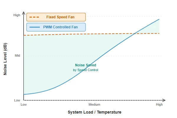
Fan speed control enables a balance between cooling performance, noise, and energy consumption. It allows a system to run quietly when idle but instantly increase airflow under heavy load, protecting critical components. This dynamic response is essential for creating an intelligent, efficient, and user-friendly product. Without it, designers are forced into a compromise: either the system is perpetually loud, or it is not cooled effectively when it matters most. Proper control provides optimal performance in both scenarios.
Implementing speed control is a significant opportunity in system design, moving beyond simple noise reduction. It facilitates an intelligent thermal management system that adapts to its environment.
Balancing Performance, Noise, and Power
At full speed, a fan provides maximum cooling but also generates the most noise and consumes the most power. For many applications, this peak performance is only needed for short periods. Speed control allows the fan to operate at a lower, quieter speed for most of its operational life, ramping up only when a sensor indicates it's necessary. This is critical for consumer electronics and office equipment where acoustic performance is a key design requirement.
Extending Fan Lifespan
A fan motor and its bearings have a finite operational life. Running a fan at 100% speed continuously places maximum mechanical stress on these components. By reducing the average operational speed, you reduce wear and tear, which can significantly extend the operational life of the fan2. For industrial equipment designed for years of continuous operation, this directly translates to greater reliability and lower maintenance costs.
| Feature | System Without Speed Control | System With Speed Control |
|---|---|---|
| Noise Level | Constantly high | Low at idle, high only when needed |
| Power Use | Always at maximum | Varies based on load, lower on average |
| Component Life | Shorter due to constant high speed | Longer due to reduced average stress |
What Is the Voltage Control Method?
For projects requiring a simple and reliable way to manage fan speed, adding complex control circuits can increase costs and introduce potential points of failure.
Voltage control, also known as linear control, adjusts a DC fan's speed by directly changing the input voltage. Lowering the voltage slows the motor, and increasing it speeds it up. It is a straightforward and highly reliable method often used in cost-sensitive applications that do not require rapid, dynamic speed changes.
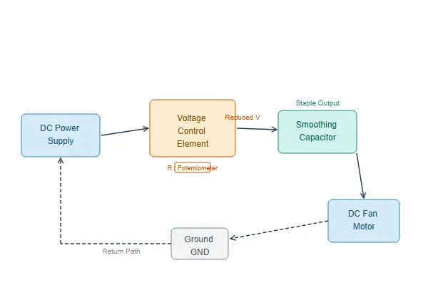
This classic approach to DC motor control is valued for its simplicity. We see this method used frequently in industrial control cabinets, power supplies, and general ventilation systems. These applications often need a "set and forget" cooling solution where the fan runs at a constant, predictable speed. The minimal electronics required make it an inherently reliable and cost-effective solution for mass production.
How It Works in Practice
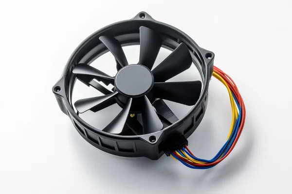
Most DC fans are rated for a specific voltage, such as 12V, but have an operating voltage range (e.g., 7V to 12V). By supplying a voltage within this range using a simple voltage regulator circuit, you can control its speed. This method is most commonly associated with standard 3-pin DC fans. The first two pins handle power and ground, while the third pin provides a tachometer signal to report the fan's rotational speed back to the system.
Advantages and Disadvantages
While simple, voltage control has trade-offs. The main risk is that if the supplied voltage drops too low, the fan motor may not have enough torque to start spinning, causing it to stall. This is a critical consideration for systems that must operate reliably at very low speeds.
| Aspect | Voltage Control |
|---|---|
| Circuit Simplicity | Very simple, low component count. |
| Cost | Low, inexpensive to implement. |
| Electrical Noise | Very quiet, no high-frequency switching. |
| Control Precision | Lower, less linear response. |
| Starting Torque | Can be low at low voltages, risking stalls. |
How Does PWM Control Work?
When a system's temperature can spike in seconds, a slow fan response can lead to performance throttling or component damage. Relying on imprecise control methods is a significant risk in such scenarios.
PWM (Pulse Width Modulation) control works by sending a rapid series of on-and-off digital signals to the fan's motor. The fan's motor driver interprets this signal to adjust the power delivered. The "duty cycle"—the percentage of time the signal is "on"—determines the average speed with great precision, while the motor itself always receives the full supply voltage during the 'on' phase.
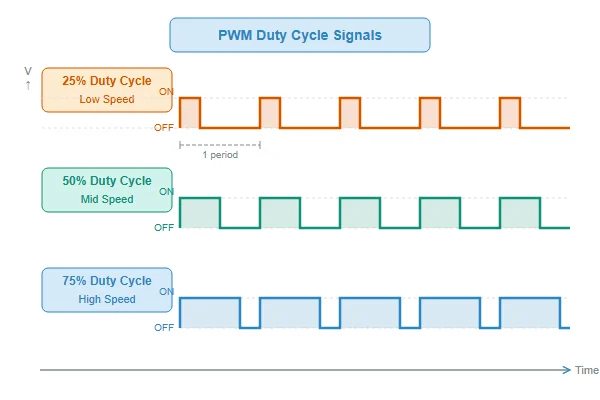
PWM is the modern standard for high-performance thermal management. For applications like CPU coolers or a fan for a high-density server, we almost always recommend PWM due to its unmatched responsiveness. The fan's speed can be adjusted almost instantly from nearly 0% to 100% in very fine steps. This allows a system's controller to execute a highly aggressive fan curve that keeps components cool under fluctuating loads, a task much more difficult to achieve with voltage control.
The Role of the Duty Cycle
The PWM signal is a square wave, and the "duty cycle" is the ratio of the pulse's 'on' time to its total period. A 100% duty cycle means the signal is always on, so the fan runs at full speed. A 25% duty cycle means the signal is on for one-quarter of the time, so the fan runs at roughly 25% of its maximum speed. Because the fan motor receives the full 12V during each 'on' pulse, it maintains high starting torque even at low speeds, eliminating the stall risk seen with voltage control. This logic is handled via a dedicated fourth wire on 4-pin fans.
Key Considerations for PWM
This precision comes with added complexity, requiring a dedicated PWM controller and a 4-pin fan. In some cases, the high-frequency switching can create a faint audible "ticking" or motor hum, though this is uncommon in quality fans.
| Aspect | PWM Control |
|---|---|
| Control Precision | Very high, allows for fine-tuning. |
| Control Range | Wide, often from 10-100% without stalling. |
| Efficiency | More efficient, especially at low speeds.3 |
| Circuit Simplicity | More complex, requires a PWM signal generator. |
| Potential Noise | Can produce faint switching noise at certain duty cycles. |
What's the Difference Between 4-Pin vs 3-Pin Connectors?
Choosing between fans advertised with 3-pin or 4-pin connectors can be confusing. Using the wrong fan for your header can limit your control capabilities or prevent the fan from operating as expected.
A 3-pin fan connector provides power, ground, and a speed signal (tachometer), and is controlled by adjusting voltage. A 4-pin connector adds a fourth wire specifically for a PWM signal, which enables much more precise and efficient digital speed control.

The number of pins on the connector directly corresponds to the available control method. A 3-pin connector is designed for the simpler voltage control method, while a 4-pin connector unlocks the advanced capabilities of PWM. Understanding this distinction helps in correctly matching the fan to your motherboard or fan controller.
A Breakdown of the Pins
The function of each pin is standardized4, which simplifies system integration. Here is a breakdown of what each pin does.
| Pin Number | 3-Pin Connector Function | 4-Pin Connector Function |
|---|---|---|
| Pin 1 | Ground (GND) | Ground (GND) |
| Pin 2 | Power (+12V / +5V) | Power (+12V) |
| Pin 3 | Tachometer Signal (reports fan speed) | Tachometer Signal (reports fan speed) |
| Pin 4 | Not Present | PWM Control Signal (sets fan speed) |
Compatibility and Common Questions
One of the most common questions is, "Can I plug a 4-pin fan into a 3-pin header?" Yes. The fan will receive power and ground but no PWM signal, so it will simply run at its full 12V speed. The reverse is also possible. Plugging a 3-pin fan into a 4-pin header will work, but only if that header supports voltage control mode (often a setting in a PC's BIOS or on the controller). If the header only supports PWM output, the 3-pin fan will just run at 100% speed.
Which Control Method Is Right for You?
Deciding between the precision of PWM and the simplicity of voltage control can be a challenge. Making the wrong choice could mean overspending on features you don't need or compromising your system's thermal performance.
Choose PWM for systems needing precise, dynamic cooling that responds to changing temperatures, such as in high-performance PCs or thermally sensitive electronics. Choose voltage control for cost-sensitive or stable-speed applications like cabinet ventilation or simple equipment where reliability and simplicity are the top priorities.
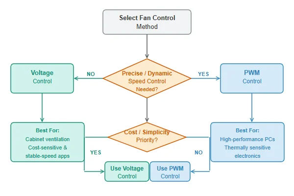
Instead of asking "which method is better?" the more effective question is "which method is right for my application?" The answer is always a trade-off. By evaluating your project's specific needs against the strengths and weaknesses of each method, the right choice becomes clear. This framework removes guesswork and helps you select a fan that provides reliable performance without adding unnecessary cost or complexity.
The Decision-Making Matrix
This matrix provides a direct comparison of the two methods across the most important factors for engineers and purchasing managers.
| Factor | Voltage Control | PWM Control |
|---|---|---|
| Precision | Lower | High |
| Cost | Lower | Higher |
| Circuit Simplicity | Simple | More Complex |
| Acoustic Profile | Generally quiet motor | Can have faint switching noise |
| Control Range | More limited (stall risk) | Very wide (no stall risk) |
Application-Based Scenarios
Let's apply this to a few real-world examples:
- High-Performance Gaming PC: The CPU and GPU generate large, fluctuating heat loads. PWM is the clear choice. It allows the system to run silently at idle and then rapidly ramp up fan speeds for maximum cooling during intense use.
- Industrial Control Cabinet: This cabinet contains electronics that need constant, stable cooling to prevent overheating, often with a fan running at a fixed 70% speed 24/7. Voltage control is ideal here. It's simple, reliable, and cost-effective for this type of steady-state operation.
- 3D Printer Enclosure: The fan needs to maintain a stable ambient temperature, but not necessarily react to second-by-second changes. Voltage control is often sufficient and cheaper. However, for cooling the printer's hotend itself where temperatures change rapidly, PWM offers better precision.
Conclusion
Choosing between PWM and voltage control is about matching the technology to your application's requirements. By carefully considering your project's needs for precision, cost, and simplicity, you can select the right fan and control method to ensure reliable and effective thermal management.
"Affinity laws", https://en.wikipedia.org/wiki/Affinity_laws. A source can illustrate the relationship between fan speed and power consumption, which is often governed by fan affinity laws, where power is proportional to the cube of the speed. This demonstrates that even small reductions in speed can lead to substantial energy savings. ↩
"One- and two-stage Arrhenius models for pharmaceutical shelf life ...", https://pubmed.ncbi.nlm.nih.gov/25358076/. A technical analysis can show that fan lifespan, often measured by L10 or MTBF, is inversely related to its average operational speed. This is because higher speeds increase wear on the bearings, which are a common point of failure. ↩
"How Pulse Width Modulation (PWM) has advantage over linear?", https://electronics.stackexchange.com/questions/751002/how-pulse-width-modulation-pwm-has-advantage-over-linear. A source can explain that in voltage control using a linear regulator, the voltage drop is dissipated as heat (Power Loss = (V_in - V_out) * I), resulting in poor efficiency at low speeds. In contrast, a PWM's switching element has minimal power loss, making it significantly more efficient across its control range. ↩
"[PDF] 4-Wire Pulse Width Modulation (PWM) Controlled Fans", https://www.mikrocontroller.net/attachment/625147/intel-4wire-pwm-fans-specs.pdf. A source can confirm the de facto industry standard for 4-pin fan connectors, such as the specification originally published by Intel, which defines the function of each pin: Ground, +12V, Tachometer, and PWM Control. ↩

Liang
I've been working with DC fans for 30 years — long enough to have seen the industry evolve from basic sleeve bearing designs to today's high-efficiency, IP68-rated systems built for the harshest environments imaginable. I founded Herays because I believed manufacturers and engineers deserved a supplier who could talk technical from day one. Not just hand over a datasheet, but actually help you select the right fan for your thermal load, your enclosure, your certification requirements. Most of what I write here comes directly from problems I've solved on the factory floor or in customer applications — medical devices, laser equipment, industrial automation, you name it. If it involves moving air efficiently and reliably, I've probably spent time thinking about it. When I'm not obsessing over airflow curves, I'm usually helping a customer figure out why their cooling system isn't performing the way their simulation said it would.
View all posts by Liang