Guessing fan size from a similar past project is how thermal problems end up discovered after the enclosure is already built, when fixing it costs far more than getting the calculation right upfront.
Calculating the right fan size starts with your system's actual thermal load in watts, converts that into a required airflow using a standard temperature-rise formula, checks that airflow against your system's static pressure resistance, and adds a reasonable safety margin -- skipping any one of these steps is the most common reason a "reasonably sized" fan turns out inadequate in practice.
- Fan sizing starts with an accurate thermal load figure in watts -- everything downstream depends on getting this number right, not estimating it loosely.
- The core airflow calculation (Q = P / (ΔT × ρ × Cp)) converts thermal load and acceptable temperature rise into a required CFM figure.
- Static pressure matters as much as CFM -- a fan that moves enough air in free space can still underperform once installed behind filters, grilles, or a restrictive enclosure.
- Choosing fan size from calculated airflow and pressure requirements together, not either alone, is what actually determines the right physical fan size and model.
- A safety margin above the calculated minimum accounts for real-world variables the calculation can't fully capture -- component tolerance, aging, and elevated ambient conditions.
Working through this calculation systematically -- rather than sizing by habit or matching a previous design -- is what actually prevents thermal problems from surfacing after a design is finalized.
Table of Contents
Why Does Fan Sizing Start With Understanding Thermal Load?
Every downstream step in fan sizing depends on having an accurate starting thermal load figure.
Thermal load is the total heat, measured in watts, that your system generates and needs to reject to maintain safe operating temperatures -- this figure comes from summing the power dissipation of all heat-generating components, and getting it wrong (usually by underestimating) is the single most common root cause of a fan turning out undersized after the fact.
Why Underestimating Thermal Load Is So Common
Component datasheets often list maximum power ratings that don't reflect real-world typical operating power, and system designers sometimes calculate thermal load from a subset of components rather than the complete system, missing smaller but cumulatively significant heat sources like voltage regulators, connectors, or PCB trace resistance losses. Building thermal load estimates from actual measured power draw under representative operating conditions, rather than relying solely on datasheet maximums, produces a more reliable starting figure for the calculations that follow.
How Does the Core Airflow Requirement Calculation Actually Work?
This formula converts your thermal load figure into the specific airflow number you need to hit.
The standard airflow calculation is Q = P / (ΔT × ρ × Cp), where Q is required airflow, P is thermal load in watts, ΔT is your acceptable temperature rise, ρ is air density, and Cp is the specific heat of air -- this formula tells you the minimum airflow needed to carry away your thermal load within your acceptable temperature rise.
Why Each Variable in This Formula Deserves Individual Attention
The thermal load (P) should come from the careful estimate discussed above, not a rough guess. The acceptable temperature rise (ΔT) is a design decision balancing component thermal limits against ambient temperature assumptions -- too aggressive a target demands more airflow (and more fan noise and cost) than necessary, while too loose a target risks inadequate cooling margin. Air density (ρ) matters more than many designers initially assume, since it decreases at altitude and with rising temperature, meaning a system sized correctly at sea level and standard ambient can become undersized at elevation or in a hot environment without adjusting for the density change.
| Variable | Meaning | Common Mistake |
|---|---|---|
| P (thermal load) | Total heat to reject, in watts | Underestimated from datasheet maximums |
| ΔT (temp rise) | Acceptable rise above ambient | Too aggressive or too loose without justification |
| ρ (air density) | Density of air at operating conditions | Assumed sea-level, ignoring altitude/temperature |
| Cp (specific heat) | Specific heat of air (~1006 J/kg·K) | Usually safe to use standard value |
How Do You Estimate Static Pressure Resistance in a Ducted or Enclosed System?
CFM alone doesn't guarantee adequate cooling if your system has meaningful airflow resistance.
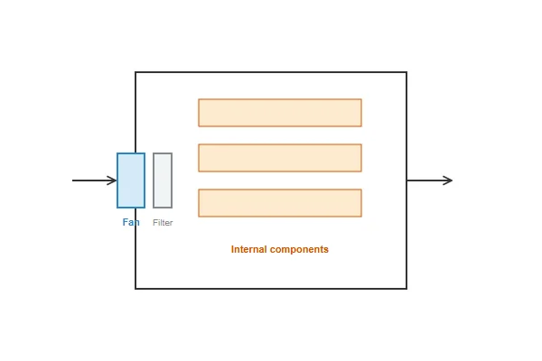
Static pressure resistance comes from every restriction in your airflow path -- filters, grilles, internal component density, duct length and bends -- and needs to be estimated or measured so you can confirm your chosen fan can actually deliver its rated CFM against that resistance, not just its unrestricted free-air CFM rating.
Why Free-Air CFM Overstates Real-World Performance
A fan's headline CFM spec is measured with no resistance at all, which rarely reflects the actual installed condition once filters, grilles, and internal component layout are accounted for. Estimating total system resistance -- from component datasheets where available, or through physical measurement of a prototype -- lets you read the fan's actual delivered CFM at that specific pressure point from its P-Q curve, rather than assuming the free-air rating applies. This is the step most frequently skipped in casual fan sizing, and it's a common reason a fan that looks adequate on paper underperforms once actually installed.
How Do You Actually Choose Fan Size From the Calculated Airflow and Pressure Requirements?
With both target numbers in hand, selecting the physical fan size and model becomes a matching exercise.
Choose a fan size and model whose P-Q curve delivers your calculated required CFM at your estimated system resistance point, generally preferring a larger fan running at lower, quieter speed over a smaller fan straining near its performance limit to hit the same operating point.
Why Larger-and-Slower Usually Beats Smaller-and-Faster
A larger fan can typically deliver a given CFM and pressure combination at a lower rotational speed than a smaller fan pushed harder to reach the same operating point, which generally translates into lower noise and reduced mechanical stress for equivalent cooling performance. This is why, when physical space allows a choice between fan sizes, selecting the larger option running comfortably within its performance range is often preferable to a smaller fan operating near its rated maximum to hit the same target.
Why Does Safety Margin Matter, and How Much Is Reasonable?
The calculated minimum airflow shouldn't be treated as your final target -- real systems need margin above it.
A reasonable safety margin -- commonly 20-30% above the calculated minimum airflow requirement -- accounts for component-to-component manufacturing tolerance, gradual performance degradation as the fan ages, dust accumulation reducing effective airflow over time, and any thermal load growth from future design revisions.
Why Margin Isn't Just Conservative Padding
Without margin, a system sized to exactly meet its calculated minimum requirement has no buffer for the fan naturally losing some performance as it ages, dust gradually restricting airflow between cleanings, or component power draw creeping up slightly in a later design revision. Building in a deliberate margin -- rather than treating the bare calculated minimum as the target -- is what keeps a system thermally healthy across its full service life and reasonable variation in real-world operating conditions, not just on day one under ideal test conditions.
We help customers work through this exact sizing calculation directly, validating our published CFM and static pressure specs on our in-house CFM airflow test system at our Dongguan facility so the numbers you calculate against reflect real, measured performance rather than optimistic marketing figures. With over 20 years of production experience under ISO 9001 certification, we're glad to review your thermal load and resistance estimates and help confirm the right fan size for your specific application.
How Do You Validate Your Calculation Against Real Prototype Data?
The calculation gets you a solid starting point, but confirming it against a real prototype is what closes the loop.
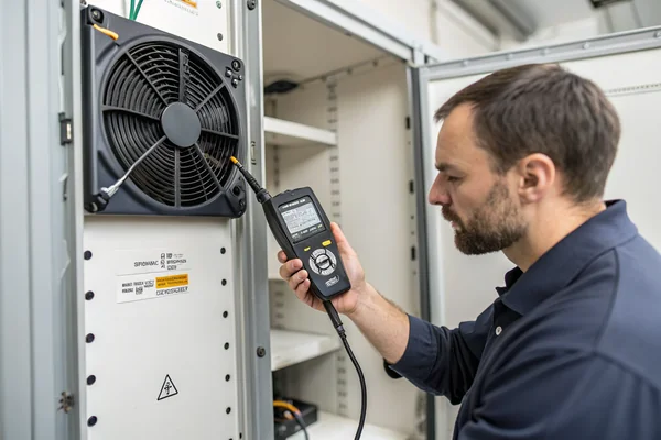
Validate a fan sizing calculation by measuring actual component temperatures on a working prototype under representative load, comparing them against your target ΔT, and adjusting fan selection if measured results diverge meaningfully from the calculated prediction -- treating the calculation as a starting hypothesis to confirm, not a final answer to trust blindly.
Why Real Measurement Catches What Calculation Alone Can't
Calculations rely on estimated thermal load and resistance figures that may not perfectly reflect the finished product's actual airflow path, component placement, or real power draw under representative software or usage conditions. Measuring actual temperatures on a working prototype, ideally under the same worst-case conditions the calculation targeted, reveals whether the estimated inputs were accurate and whether the chosen fan is actually delivering the margin the calculation predicted -- catching a sizing gap during prototyping is far cheaper than discovering it after production has started.
FAQ
What's a reasonable default acceptable temperature rise (ΔT) if I don't have a specific component limit to design against?
This varies significantly by application, but many general electronics cooling designs target a rise in the range of 10-20°C above ambient as a starting point, adjusted based on the specific thermal limits of the most sensitive component in the system.
Do I need to measure static pressure resistance directly, or can I estimate it from component specs?
Direct measurement on a prototype is more reliable when available, but reasonable estimates can be built from filter and grille manufacturer specs plus general assumptions about internal component density if a prototype isn't yet available.
How does this calculation change for a system with multiple fans?
Multiple fans in parallel generally increase total airflow at a given pressure point, while fans in series can increase pressure capability -- the specific combined effect depends on the fan curves and configuration, and is worth calculating explicitly rather than simply assuming proportional scaling.
Is it possible to oversize a fan, and does that cause problems?
Yes -- an excessively oversized fan wastes cost, adds unnecessary noise and power draw, and doesn't meaningfully improve cooling once airflow needs are already well met. The goal is appropriate sizing with reasonable margin, not maximizing airflow.
Does this calculation apply the same way to blowers as to axial fans?
The core thermal load and airflow calculation applies similarly, but blower selection additionally needs to account for the generally higher static pressure characteristics blowers are chosen for for restrictive applications -- the P-Q curve matching step matters even more for blower sizing.
How often should fan sizing be revisited during a product's development?
Whenever thermal load estimates change meaningfully -- new components added, power consumption figures updated, or enclosure design changes affecting airflow resistance -- revisiting the sizing calculation rather than assuming the original fan choice still holds.
Correct fan sizing comes down to working through thermal load, airflow, static pressure, and margin systematically, rather than sizing by habit or a rough estimate. At Herays, our Dongguan facility validates fan performance specs on in-house testing equipment so the numbers you calculate against are real, backed by over 20 years of experience under ISO 9001 certification. If you're working through a fan sizing calculation for a specific application, we're glad to help confirm the right fit.

Liang
I've been working with DC fans for 30 years — long enough to have seen the industry evolve from basic sleeve bearing designs to today's high-efficiency, IP68-rated systems built for the harshest environments imaginable. I founded Herays because I believed manufacturers and engineers deserved a supplier who could talk technical from day one. Not just hand over a datasheet, but actually help you select the right fan for your thermal load, your enclosure, your certification requirements. Most of what I write here comes directly from problems I've solved on the factory floor or in customer applications — medical devices, laser equipment, industrial automation, you name it. If it involves moving air efficiently and reliably, I've probably spent time thinking about it. When I'm not obsessing over airflow curves, I'm usually helping a customer figure out why their cooling system isn't performing the way their simulation said it would.
View all posts by Liang