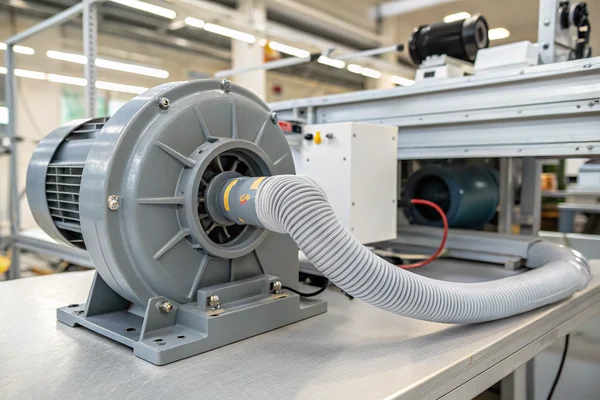
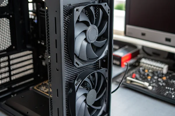
Electronics cooling failures don't announce themselves -- they accumulate quietly until a component throttles, corrupts data, or fails outright. A standard axial fan often can't solve the problem. A blower can.
A DC brushless blower moves air in a fundamentally different way than an axial fan -- drawing air in axially and exhausting it radially -- making it the right choice when electronics cooling requires directed, pressure-driven airflow through tight enclosures, dense PCBs, or restricted duct paths where a standard fan simply can't build enough static pressure to push through.
- DC brushless blowers differ from axial fans in airflow direction: they intake axially and exhaust radially, which is what allows them to generate the static pressure needed for restrictive cooling paths.
- Tight enclosures, dense PCB layouts, and forced-duct cooling architectures almost always require a blower rather than an open-frame axial fan.
- Blower sizing depends on the thermal load, the system's resistance curve, and the operating point where the blower's P-Q curve actually intersects that resistance -- not just peak CFM spec.
- Mounting orientation, inlet clearance, and outlet ducting geometry all significantly affect delivered airflow; getting these wrong is a common reason a correctly sized blower underperforms in the field.
- Noise and power budget are not afterthoughts -- they constrain which operating point on the P-Q curve is actually usable, and both should be specified before a blower is selected, not after.
Understanding when and why a blower outperforms an axial fan -- and how to specify one correctly -- is the difference between a cooling system that works on a bench and one that works in production.
Table of Contents
Why Does Electronics Cooling Sometimes Demand a Blower Instead of a Fan?
Not every thermal problem is created equal, and using the wrong airflow device makes cooling harder, not easier.
An axial fan moves air parallel to its axis and excels at high-volume open-air flow, but generates little static pressure -- once airflow resistance rises above a low threshold, its effective airflow collapses. A DC brushless blower generates substantially higher static pressure at equivalent sizes, making it the correct tool whenever the airflow path is restricted.
The Fundamental Difference Is Pressure, Not Speed
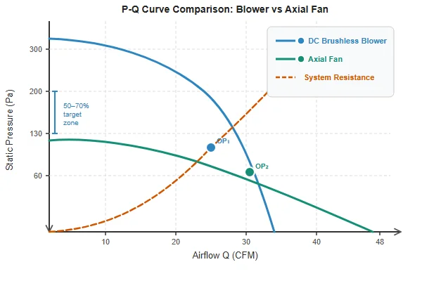
The distinction is rooted in how each device interacts with system resistance. An axial fan's P-Q curve1 drops steeply under resistance -- add a filter, a duct bend, or a tightly packed PCB assembly in the airflow path, and delivered airflow falls sharply. A centrifugal blower maintains useful airflow across a much wider range of static pressure, because its impeller design converts rotational energy into both velocity and pressure rise rather than velocity alone.
This matters practically in electronics cooling because modern assemblies -- power supplies, embedded computing boards, medical devices, industrial controllers -- rarely present an open, unobstructed airflow path. Heatsinks, cable bundles, daughterboards, and enclosure walls all add resistance. In these environments, specifying an axial fan based on its open-air CFM rating and expecting that airflow to reach the critical components is an engineering error that gets discovered during thermal validation, not before.
A DC brushless blower is also the natural choice whenever the thermal management design calls for directed, single-inlet/single-outlet forced airflow -- for example, pushing air along a heatsink channel or through a ducted path to a specific hot spot -- rather than general circulation inside an enclosure.
| Application Type | Axial Fan | DC Brushless Blower |
|---|---|---|
| Open-air general ventilation | Good fit | Overkill |
| Filtered enclosure with restricted inlet | Poor -- CFM drops sharply | Good fit |
| Ducted heatsink channel | Poor | Good fit |
| Dense PCB with heatsink arrays | Marginal | Correct choice |
| High ambient temperature, sustained load | Depends on restriction | Preferred |
How Do You Direct Airflow Through Tight Enclosures With a Blower?
Getting air to the right place inside a restricted enclosure is as much a ducting and geometry problem as it is a fan selection problem.
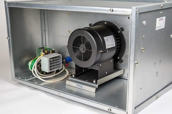
A DC brushless blower's radial exhaust makes it inherently directional -- the outlet can be aimed and ducted to concentrate airflow at specific hot zones rather than relying on general circulation. This is its core advantage in tight enclosures, but only if the inlet has adequate clearance and the outlet path doesn't introduce avoidable resistance.
Inlet Clearance Is Where Most Installations Go Wrong
The blower's axial inlet needs unobstructed space to draw air in. A common field mistake is mounting the blower flush against a panel or component in a way that chokes the inlet, reducing effective airflow by a significant margin even when the rest of the installation looks correct. As a general practice, inlet clearance of at least one inlet diameter is the minimum -- more is better where the enclosure geometry allows it.
Outlet ducting geometry matters almost as much. Sharp 90-degree turns immediately at the blower outlet, undersized duct cross-sections, or abrupt expansions all add resistance that pushes the operating point up the P-Q curve toward lower airflow. If ducting is necessary, gentle radius bends, smooth interior surfaces, and duct cross-sections matched to the blower's outlet area preserve more of the delivered airflow than tight or mismatched ducting.
For enclosures with multiple heat sources, partial internal baffling -- even simple sheet-metal guides -- can be used in combination with the blower to route airflow past the highest-dissipation components first, rather than letting it take the path of least resistance through the cooler parts of the enclosure. This kind of airflow architecture, designed around the blower's directional exhaust, is what separates a competent thermal design from one that passes thermal validation at the bench but runs hot in the field.
How Do You Actually Size a Blower to Your Thermal Load?
Sizing a blower on CFM alone is the most reliable way to end up with a cooling system that works on paper and fails in production.
Correct blower sizing requires calculating the thermal load in watts, determining the required airflow to carry that heat at acceptable temperature rise, then plotting that requirement against the system's actual resistance curve to find the real operating point on the blower's P-Q curve -- not just matching a peak CFM spec to a rough airflow estimate.
Start With the Heat, Not the Fan Spec Sheet
The foundational calculation: required airflow (in CFM) equals heat dissipation in BTU/hr divided by (1.08 × allowable temperature rise in °F). For a system dissipating 100W (~341 BTU/hr) with a 10°C (18°F) allowable temperature rise, that works out to roughly 17.5 CFM at the component. This number gives the airflow target, but it says nothing about the pressure required to actually deliver that airflow through the enclosure.
The system resistance curve -- how static pressure requirement rises as airflow increases through a given enclosure geometry -- must be estimated or measured for the actual assembly. The ANSI/AMCA Standard 210 defines laboratory methods for characterizing fan and blower P-Q performance, and the operating point where a blower's published P-Q curve intersects the system curve is the true delivered airflow -- which is almost always lower than the blower's open-air maximum. Sizing to peak CFM without accounting for system resistance is what produces undersized cooling in practice.
Leave a margin. A blower operating near the knee of its P-Q curve -- close to its peak pressure capability -- is working near its efficiency limit and typically generating more noise. Targeting an operating point at roughly 50–70% of the blower's maximum pressure capability at the required airflow gives realistic headroom for filter loading, component tolerance variation, and aging.
What Mounting and Ducting Choices Matter Most in Practice?
Physical installation details have a larger effect on delivered airflow than most engineers expect before they measure it.
Vibration isolation, mounting orientation, inlet/outlet clearance, and duct geometry together determine how much of a blower's rated performance actually reaches the target components -- poor installation practice can negate a correct blower selection entirely, and these factors should be designed in from the start rather than corrected after thermal testing fails.
Vibration Isolation Protects Both the Blower and the Enclosure
DC brushless blowers are rotating machines, and their vibration transmits readily into metal enclosures, which can act as resonators and amplify the noise. Soft-mount techniques -- rubber gaskets, anti-vibration grommets at mounting points -- are standard practice for noise-sensitive applications and also reduce mechanical fatigue on solder joints near the blower mounting location. The specific durometer of the isolation material affects both isolation effectiveness and the blower's positional stability; a balance between compliance and rigidity is usually found at medium-durometer silicone or EPDM mounts.
Mounting orientation affects condensate management in some environments. Most DC blowers are designed to run in any orientation, but if the application environment involves humidity cycling or potential condensation, inlet orientation should avoid direct exposure to drip paths. This is particularly relevant in industrial enclosures where the blower may run intermittently, allowing condensation to form during off cycles.
For sealed or partially sealed enclosures, a pressure-balanced approach -- blower on the inlet pushing air through the enclosure, with a passive exhaust vent sized to avoid creating a back-pressure restriction -- generally outperforms a purely exhaust-mounted configuration in terms of delivering clean, filtered air past sensitive components.
How Do You Balance Airflow, Noise, and Power Budget Without Compromising Any of Them?
Airflow, noise, and power are not independent -- changing one moves the others, and the tradeoffs need to be resolved before a blower is specified, not after.
Noise and power draw both increase as a blower is pushed harder toward its pressure limit or spun faster to compensate for an undersized selection -- the correct approach is to size generously so the operating point sits in the efficient mid-range of the P-Q curve, then use PWM speed control to trim airflow and noise to the actual demand rather than running at a fixed aggressive speed.
PWM Control Changes the Equation Significantly
A DC brushless blower with PWM speed control gives the system designer a real lever for balancing noise against cooling performance across different operating conditions. Running the blower at reduced speed during low-load conditions -- when ambient temperature is moderate and component dissipation is low -- meaningfully reduces both acoustic output and power draw without compromising thermal protection, because the cooling requirement is genuinely lower. Thermal sensors tied to the PWM control signal can automate this, ramping the blower only as heat actually builds.
The power budget constraint is particularly important in battery-powered or portable electronics, where blower power draw directly reduces runtime. In these applications, selecting a blower whose efficient operating point aligns with the actual cooling requirement -- rather than one that's oversized and therefore always throttled back -- minimizes the power penalty. Higher-efficiency brushless motor designs, specifically optimized for their target speed range, make a measurable difference here compared to generic blower selections.
Noise targets should be established as a hard specification -- in dB(A) at a defined distance -- before blower selection begins, not as a soft preference to be revisited if the selected blower turns out to be louder than expected. This constraint directly affects which operating point on the P-Q curve is actually usable and therefore feeds back into sizing.
What Are the Real Procurement Risks When Sourcing a DC Brushless Blower?
Datasheet specs and delivered performance frequently diverge, and the procurement process for blowers has specific risks worth understanding before committing to a supplier.
The most common procurement failure modes are specifying only open-air CFM (which doesn't predict restricted-path performance), accepting a datasheet P-Q curve without requiring it to be validated under your actual system conditions, and selecting a standard catalog blower when the application's geometry actually requires a custom inlet or outlet configuration.
P-Q Curve Validation Is Non-Negotiable for Critical Applications
A published P-Q curve is only meaningful if it was generated using a recognized test standard -- the ANSI/AMCA Standard 210 methodology defines how these tests should be conducted to produce comparable, repeatable results. Asking a supplier whether their published curves are derived from AMCA-method testing, or from a simpler proprietary bench test, is a legitimate and practical due diligence question. Curves produced from informal internal testing may look similar on paper but represent a different and less reliable level of assurance.
For applications with tight form factors, confirm the physical dimensions of the blower's inlet and outlet -- not just its overall footprint -- before finalizing a selection. Catalog drawings sometimes show the housing envelope without clearly indicating the effective inlet clearance zone required for rated performance, which can create interference problems during mechanical integration that aren't visible until a prototype is assembled.
Minimum order quantities, lead times, and supply continuity all matter differently for blowers than for commodity axial fans. A custom pitch or blade geometry change, if your application requires one, adds tooling lead time that should be factored into the project schedule from the start.
Our DC High-Speed Vortex Blower Fan line is engineered specifically for the electronics cooling use cases described here -- tight enclosures, directed pressure-driven airflow, and noise-sensitive industrial applications. Every blower we produce is validated on our in-house CFM airflow test system and anechoic noise test chamber as part of our ISO 9001 quality process, giving us verified P-Q and acoustic data rather than calculated estimates. If your application has a specific static pressure target, noise budget, or form factor constraint, we can discuss the design tradeoffs and whether a standard catalog selection or a custom configuration is the better fit.
What Common Failure Modes Should Engineers Anticipate With DC Brushless Blowers in Electronics Cooling?
Blowers fail in predictable ways, and most failures can be anticipated at the design stage rather than discovered in the field.
The most common DC brushless blower failure modes in electronics cooling applications are bearing wear from inadequate inlet clearance (causing recirculation heating), impeller fouling from unfiltered airflow, thermal overstress from operating too close to the stall point on the P-Q curve, and connector or cable fatigue from vibration not isolated at the mounting points.
Most Failures Trace Back to an Installation or Sizing Decision
Bearing life in a DC brushless blower is highly sensitive to operating temperature -- a blower that draws in warm recirculated exhaust air, because its inlet is positioned too close to the enclosure's hot exhaust zone, runs hotter than its rated thermal envelope and ages faster. This is a system layout problem, not a blower defect, but it shows up as a blower failure in the field.
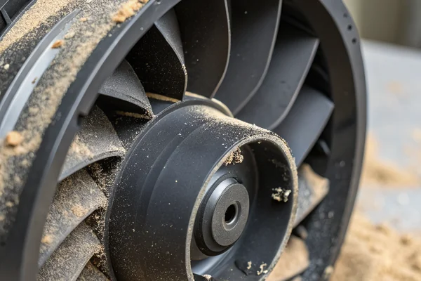
Impeller fouling from dust and particulates is the other major life-limiting factor in industrial environments. A blower operating without inlet filtration in a dusty environment will accumulate deposits on the impeller blades over time, shifting the effective pitch and degrading performance while also adding imbalance that accelerates bearing wear. Inlet filtration with a defined maintenance interval is the standard mitigation, but the filter's added resistance must be included in the original P-Q operating point calculation -- a filter loaded to 50% capacity may add measurably more restriction than a clean filter.
Stall-point operation -- where the system resistance is high enough to push the blower toward the far-left end of its P-Q curve -- generates elevated noise, heat, and vibration, and is mechanically hard on the motor. Designs that allow the system resistance to vary (for example, a filter that loads progressively) should verify that the operating point remains in the stable region of the P-Q curve at maximum expected filter loading, not just when clean.
FAQ
What's the practical difference between a DC brushless blower and a DC axial fan for electronics cooling?
An axial fan moves air parallel to its axis and works best in open, low-resistance paths. A DC brushless blower draws air in axially but exhausts radially, generating significantly higher static pressure -- which is what allows it to push airflow through the restricted paths typical in electronics enclosures.
Can I use PWM control with a DC brushless blower the same way I would with an axial fan?
Yes -- DC brushless blowers with PWM input work similarly to PWM-controlled axial fans. Speed responds to the duty cycle signal, allowing thermal management firmware to ramp airflow up or down based on real-time temperature feedback. Confirm the blower's supported PWM frequency range with the supplier before integrating.
How do I know if my enclosure's system resistance curve is within a blower's capable range?
The blower's P-Q curve defines its capability envelope. If your estimated or measured system resistance at the required airflow exceeds the blower's maximum static pressure, that blower can't deliver the needed airflow regardless of speed. Work backward from the system resistance curve to find the minimum blower pressure capability required.
Is a higher-CFM blower always the safer choice if I'm uncertain about system resistance?
Not necessarily -- an oversized blower running well below its capability wastes power, may run louder than necessary, and provides no real margin benefit if the constraint is static pressure rather than volume. Sizing correctly to the operating point, with appropriate margin, is more useful than simply selecting the highest CFM option available.
Does blade material or impeller construction affect blower performance at elevated temperatures?
Yes, practically. Plastic impellers can exhibit slight geometric changes at sustained elevated temperatures, affecting both aerodynamic performance and balance. For applications with elevated ambient temperatures or high-duty-cycle operation, confirming the impeller material's rated thermal range with the supplier is worthwhile.
How much inlet clearance does a DC brushless blower actually need to perform to its rated spec?
As a working guideline, a minimum clearance equal to the inlet diameter is a commonly applied starting point, though specific manufacturer recommendations vary. Restricted inlet clearance is one of the most consistent causes of below-spec airflow in installed systems.
Should noise spec be verified at the blower's actual operating point, not its rated maximum?
Yes -- published dB(A) specs are typically measured at a specific operating condition, often maximum speed. If the application runs the blower at a reduced PWM duty cycle, the actual noise level will be lower; if it runs near maximum pressure, it will typically be higher. Request noise data at the expected operating point if acoustic compliance is a hard requirement.
Selecting and integrating a DC brushless blower for electronics cooling is a systems problem, not just a component selection. Thermal load, system resistance, mounting geometry, and noise budget all interact -- and getting any one of them wrong undermines the rest. Herays has engineered DC blowers and axial fans from our Dongguan facility for over 20 years, under ISO 9001, ISO 14001, QC 080000, and IATF 16949 certification. If your thermal design has specific pressure, airflow, or noise constraints, contact us to discuss the right configuration for your application.
P-Q curve (pressure-volume curve) is the graphical relationship between a fan or blower's static pressure output and volumetric airflow across its operating range. In restrictive electronics cooling applications, the intersection of this curve with the system's resistance curve determines actual delivered airflow, which is almost always lower than the open-air maximum shown on a datasheet. ↩

Liang
I've been working with DC fans for 30 years — long enough to have seen the industry evolve from basic sleeve bearing designs to today's high-efficiency, IP68-rated systems built for the harshest environments imaginable. I founded Herays because I believed manufacturers and engineers deserved a supplier who could talk technical from day one. Not just hand over a datasheet, but actually help you select the right fan for your thermal load, your enclosure, your certification requirements. Most of what I write here comes directly from problems I've solved on the factory floor or in customer applications — medical devices, laser equipment, industrial automation, you name it. If it involves moving air efficiently and reliably, I've probably spent time thinking about it. When I'm not obsessing over airflow curves, I'm usually helping a customer figure out why their cooling system isn't performing the way their simulation said it would.
View all posts by Liang