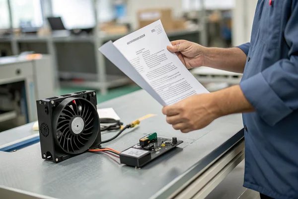
A customer's board once failed EMC certification three times before anyone thought to check the cooling fan. The fan itself worked perfectly. It was also radiating enough switching noise to interfere with a sensor circuit six inches away, and nobody had budgeted time to debug it that late in the project. EMI from a DC fan is one of those problems that's cheap to prevent and expensive to chase down after the fact.
- Every brushless DC fan is a small switching power supply -- the driver IC chops current at high frequency to spin the motor, and that switching is the actual source of the EMI, not the motor itself.
- Conducted EMI travels back down the power leads into your system; radiated EMI comes off the cable and PCB traces like a tiny antenna. They need different fixes.
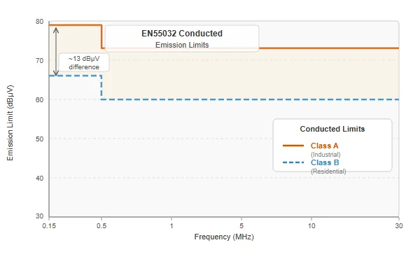
- EN55032 (formerly EN55022) and CISPR 32 set the conducted/radiated emission limits most B2B electronics need to meet, and Class B (residential) is meaningfully stricter than Class A (industrial).
- A fan that passes EMC testing on its own bench can still fail once it's mounted three inches from a sensitive analog or RF circuit in your actual enclosure -- standalone compliance data isn't a guarantee.
- Ferrite beads and filter capacitors fix a surprising amount of this cheaply, but only if they're specified before the board layout is finalized, not after a failed test.
Table of Contents
What Is EMI in DC Fans?
Electromagnetic interference, in this context, is unwanted electrical noise generated by the fan's motor drive circuit that either travels through its wires into the rest of your system (conducted EMI) or radiates off the fan and its cable as electromagnetic energy (radiated EMI)1. Neither is a defect -- it's an unavoidable byproduct of how a brushless DC motor actually works.
The reason this matters to you as a buyer is simple: your product has to pass an EMC test before it ships, and the cooling fan is a real, measurable contributor to both the conducted and radiated noise floor. It's rarely the biggest contributor in a complex product, but it's one of the easier ones to fix cheaply if you catch it early, and one of the more annoying ones to chase down if you don't.
How Do Brushless DC Fans Generate EMI?
A brushless DC fan doesn't have a simple DC motor spinning off a steady current. Inside it is a small driver IC that switches current through the motor windings in a specific commutation sequence, and that switching happens at a high enough frequency and speed to generate harmonics well up into the RF spectrum.
Every time the driver switches a winding on or off, the fast rise and fall time of that current (a high di/dt) creates a broadband noise spike. The fundamental switching frequency plus its harmonics is what conducted emission testing picks up on the power leads, while the same fast edges on PCB traces and wire runs act as small unintentional antennas for radiated emission testing. A PWM-controlled fan adds a second noise source on top of this: the PWM control line itself is a square wave, and square waves are rich in harmonics.
What Does EN55032 / CISPR 32 Compliance Actually Require?
EN55032 (the standard that replaced EN55022) and its international counterpart CISPR 32 define conducted and radiated emission limits for multimedia and IT equipment, and most B2B electronics products end up needing to meet one or both, directly or as part of a larger system-level test.
The practical distinction that trips people up is Class A versus Class B. Class A covers equipment intended for industrial or commercial environments and has looser limits. Class B covers equipment intended for residential environments and is noticeably stricter, on the assumption that a noisy device sitting in someone's living room is more likely to interfere with a neighbor's radio or TV than the same device sitting in a factory. If your end product is going into a home, expect Class B limits; if it's staying in an industrial or commercial setting, Class A usually applies.
A fan supplier who can hand you real conducted and radiated emission test data -- not just a compliance statement -- lets you model how much noise budget the fan is actually using up before you've built a single prototype.
We've been building DC fans for over 20 years, and EMI complaints almost always show up after a customer's board has already failed a system-level EMC test -- by then it's a scramble. Our Dongguan facility runs every fan design through conducted and radiated emission testing as part of our IATF 16949 and ISO 9001 validation process, and we can share that raw test data, not just a pass/fail statement, so your EMC engineer can actually budget the fan's contribution against your system-level limit before layout is finalized.
What Are the Most Effective EMI Reduction Design Tips?
Most of the effective fixes here are cheap, and most of them need to happen before the board layout is frozen, not after a failed test.
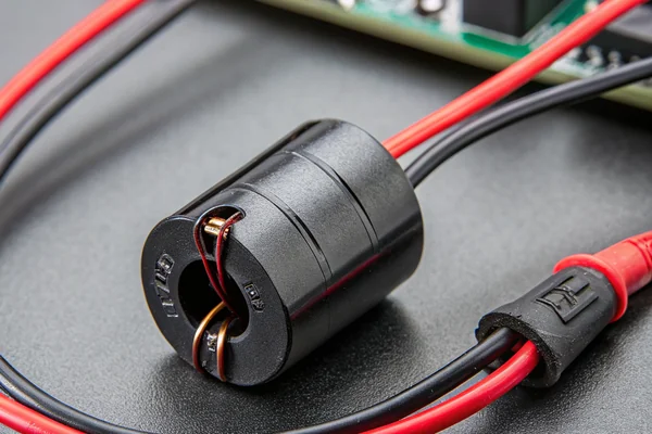
Ferrite beads or chokes on the power leads are the simplest first step -- they add impedance at high frequencies without affecting the DC power the motor actually needs. Keeping power and signal traces short, using a solid ground plane, and twisting the PWM/tach signal pair with its return line all reduce how effectively those traces act as antennas. Some driver ICs support spread-spectrum modulation of the switching frequency, which doesn't reduce total noise energy but spreads it across a wider band instead of concentrating it at one sharp peak that's more likely to exceed a narrowband limit.
If your fan is going into a metal enclosure or a metal-frame fan rather than a plastic one, that frame itself can act as partial shielding for radiated emissions, which is worth factoring in if EMI margin is tight and you're already choosing frame material for thermal or vibration reasons.
When Should You Use Shielding vs Filter Capacitors?
Shielding and filter capacitors solve different halves of the same problem, and it's worth being clear about which one you actually need.
Filter capacitors -- typically an X capacitor across the power lines and Y capacitors from each power line to a reference ground -- primarily attack conducted EMI by giving high-frequency noise a low-impedance path back to its source instead of letting it propagate down the power cable. They're inexpensive and easy to add near the fan's power input. Shielding, whether it's a shielded cable, a metal fan frame, or a shielded enclosure, primarily attacks radiated EMI by containing or reflecting the electromagnetic energy before it escapes into free space.
| Problem | Best First Fix | Typical Cost |
|---|---|---|
| Conducted EMI on power leads | Ferrite bead + filter capacitors | Low |
| Radiated EMI from cable/traces | Shielded cable, short trace runs | Low-Medium |
| Radiated EMI from the fan body | Metal frame or enclosure shielding | Medium |
| Marginal failure near a limit line | Spread-spectrum PWM frequency | Design-dependent |
In practice, most fans that fail conducted testing need better filtering, not more shielding, while most fans that fail radiated testing at a specific frequency need better cable/trace management or an enclosure fix rather than a bigger capacitor.
FAQ
Does a higher-quality fan automatically mean lower EMI? Not directly. EMI is more a function of the driver IC's switching characteristics and the fan's internal layout than overall build quality. A well-designed budget fan can outperform a poorly EMI-optimized premium one on this specific spec.
Can I fix an EMI failure without changing the fan at all? Often yes, through added filtering, shielding, or cable routing changes on your side. But if the fan itself is a significant contributor, working with the supplier on a version with better internal suppression is usually more effective than trying to filter it out entirely downstream.
Does PWM speed control make EMI worse than voltage control? It adds an additional noise source (the PWM square wave itself), so all else equal, a PWM fan has one more thing to manage than a voltage-controlled fan. It's rarely a reason to avoid PWM, since the speed control benefits usually outweigh the added EMI design work.
What test data should I ask a fan supplier for? Ask for conducted and radiated emission test reports against the specific standard your product needs to meet (EN55032/CISPR 32 for most IT/electronics, CISPR 25 for automotive), not just a general compliance statement.
Is EMI worse at higher fan speeds or higher RPM ratings? Generally yes, since higher-speed motors often require faster switching, which pushes noise energy higher in frequency. This isn't a hard rule across every design, but it's worth checking emission data specifically at your operating speed, not just the fan's rated maximum.
Do brushless fans always need an EMI filter, or only in sensitive applications? Most fans ship with at least basic filtering built in. Whether you need additional filtering depends on your system's specific limit and how much margin the fan design already has -- there's no universal answer independent of your actual test results.
EMI from a cooling fan is a solvable problem, but only if it's on the table early. Asking a supplier for real conducted and radiated emission data before you finalize your board layout costs nothing and can save weeks of debugging later.
At Herays, our Dongguan facility validates every fan design against EN55032/CISPR 32 conducted and radiated emission limits as part of our IATF 16949 and ISO 9001 quality process, and we share the actual test data with customers who need to budget it into their own system-level compliance.
"Electromagnetic interference", https://en.wikipedia.org/wiki/Electromagnetic_interference. Electromagnetic interference is disturbance generated by an external source that affects an electrical circuit through electromagnetic induction, electrostatic coupling, or conduction. ↩

Liang
I've been working with DC fans for 30 years — long enough to have seen the industry evolve from basic sleeve bearing designs to today's high-efficiency, IP68-rated systems built for the harshest environments imaginable. I founded Herays because I believed manufacturers and engineers deserved a supplier who could talk technical from day one. Not just hand over a datasheet, but actually help you select the right fan for your thermal load, your enclosure, your certification requirements. Most of what I write here comes directly from problems I've solved on the factory floor or in customer applications — medical devices, laser equipment, industrial automation, you name it. If it involves moving air efficiently and reliably, I've probably spent time thinking about it. When I'm not obsessing over airflow curves, I'm usually helping a customer figure out why their cooling system isn't performing the way their simulation said it would.
View all posts by Liang