Most engineers know they need "more airflow" and reach for an axial fan by habit. That instinct works until it doesn't -- until a duct gets long, a filter gets restrictive, or a heat source gets dense enough that moving air volume alone stops being the problem and moving air through resistance becomes the real challenge.
A DC brushless blower fan uses a centrifugal impeller spinning inside a scroll housing to convert rotational energy into directed, high-pressure airflow -- making it fundamentally different from an axial fan in both how it moves air and where it performs well, specifically in applications with high static pressure demands.
- A blower fan is defined by its centrifugal impeller and scroll housing, which redirect airflow 90 degrees from intake to exhaust -- unlike axial fans, which push air straight through along the rotation axis.
- The centrifugal impeller accelerates air outward by centrifugal force and then converts that velocity into static pressure through the scroll housing geometry, making blowers inherently suited to restrictive airflow paths.
- DC brushless motor commutation eliminates the brushes that wear down in brushed motors, extending service life and enabling precise speed control through PWM or analog signal -- critical in duty-cycle-intensive applications.
- Blowers consistently outperform axial fans where back-pressure is high: ducted systems, filtered enclosures, medical devices, and anywhere the airflow path itself adds significant resistance.
- Selecting between a blower and an axial fan requires reading the application's system resistance curve against the fan's P-Q curve -- not just comparing CFM specs on a datasheet.
Understanding where and why blowers work differently from axial fans isn't academic -- it directly affects whether the thermal management system you specify will hold up under real operating conditions or fail quietly at the worst moment.
Table of Contents
What Actually Makes a Blower a Blower -- Not Just a Different Axial Fan?
Two fans can sit side by side on a shelf and look superficially similar. The difference that matters is entirely about geometry.
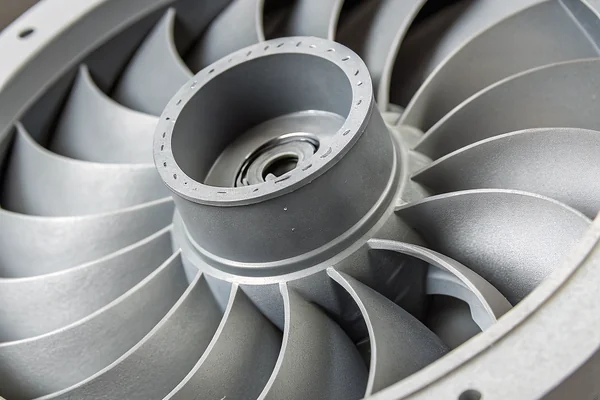
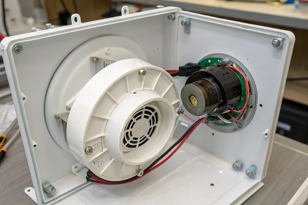
A blower fan is defined by two structural features absent in axial fans: a centrifugal impeller that moves air radially outward rather than axially forward, and a scroll-shaped housing that captures and redirects that radially accelerated air into a single directed exhaust port -- typically at 90 degrees to the intake.
Why the Scroll Housing Is the Defining Feature, Not Just the Impeller
The impeller alone doesn't make a blower. What makes the blower architecture distinct is the scroll housing -- sometimes called a volute -- that surrounds the impeller. As the impeller throws air outward by centrifugal action, the scroll housing collects that air along an expanding spiral path and channels it toward a single exhaust opening. This geometry does two things simultaneously: it converts the high-velocity radial airflow into static pressure (through the expanding cross-section, following basic Bernoulli principles), and it concentrates that pressurized output into a narrow, directed stream rather than a broad cone.
An axial fan has no equivalent structure. Air enters and exits along the same axis, moving in a roughly parallel column. There's no geometric mechanism to build up static pressure the way a scroll housing does, which is why axial fans and blowers occupy genuinely different positions on the pressure-versus-airflow performance map -- not just different points on the same curve.
| Feature | DC Brushless Blower | DC Axial Fan |
|---|---|---|
| Airflow direction | Radial (90° turn from intake to exhaust) | Axial (straight through) |
| Housing type | Scroll / volute | Open frame or simple ring |
| Pressure capability | High static pressure | Low to moderate static pressure |
| Airflow volume at zero resistance | Moderate | High |
| Typical application | Ducted, filtered, restrictive paths | Open-air, unrestricted ventilation |
How Does the Centrifugal Impeller Actually Move Air?
The impeller's action looks simple from the outside. The physics behind it explain why it generates pressure so effectively.
The centrifugal impeller accelerates air inward through the eye (center) and then outward at high velocity toward the housing wall by centrifugal force -- that outward velocity is then converted into static pressure as the air decelerates and expands through the scroll housing geometry, following the same principle as a centrifugal pump.
From Velocity to Pressure: The Conversion the Scroll Housing Performs
When the impeller spins, low pressure at the eye draws air in axially through the intake opening. The rotating blades then impart kinetic energy to that air, accelerating it radially outward. By the time air reaches the impeller tip, it's moving at high velocity -- but velocity alone isn't useful for pushing air through a restrictive system. What the scroll housing does is convert that kinetic energy into static pressure through an expanding spiral cross-section: as the air slows down (constrained to follow the expanding scroll path), its dynamic pressure converts to static pressure, in the same way a diffuser works in a turbine or compressor.
This energy conversion process is efficient enough that blowers can generate static pressure values several times higher than a comparably sized axial fan spinning at the same speed. The tradeoff is that the scroll geometry constrains airflow to a single outlet direction, which is why blowers are less convenient than axial fans for applications requiring broad, distributed air distribution -- but in applications where all the air needs to go somewhere specific, that constraint is actually useful.
Why Do Blowers Generate So Much More Static Pressure Than Axial Fans?
The pressure gap between blowers and axial fans isn't a minor spec difference -- it's a fundamental consequence of how each moves air.
Blowers generate higher static pressure than axial fans because the centrifugal impeller-plus-scroll architecture is specifically designed to convert rotational energy into pressure buildup rather than bulk airflow, while axial fans lack the housing geometry needed to develop or sustain pressure against significant back-pressure.
Why Axial Fans Stall While Blowers Keep Pushing
An axial fan's P-Q curve1 drops steeply as system resistance rises -- add enough back-pressure and the fan stalls, delivering close to zero useful airflow while still consuming power and generating noise. This happens because axial fans aren't built to develop pressure; they're built to accelerate air columns. As resistance rises, that column stalls.
A blower's P-Q curve retains useful airflow much further into high-resistance territory because the centrifugal mechanism actively builds pressure as part of normal operation. The scroll housing gives the pressurized air somewhere to go -- through the exhaust port and into the downstream system -- rather than recirculating or stalling. For applications like dense filter media, long duct runs, or tightly sealed enclosures, this pressure retention is the difference between a functional cooling solution and one that gradually degrades as filters load up or back-pressure rises over time.
Where Do Axial Fans Actually Fall Short -- and Blowers Take Over?
Knowing which scenarios genuinely require a blower saves time and avoids quiet thermal failures.
Axial fans fall short wherever the airflow path adds significant resistance -- ducted systems, high-efficiency filters, dense heat exchanger fins, and sealed enclosures with restricted outlets -- because their pressure capability drops off too quickly under back-pressure to sustain adequate airflow at the operating point that actually matters.
The Failure Mode Engineers Most Often Overlook
The most common mistake isn't choosing an axial fan for a genuinely open-air application -- it's specifying an axial fan for a system that looks relatively open but has more cumulative resistance than expected. A filter plus a duct bend plus a heat exchanger stack can add up to back-pressure levels that push an axial fan well past its useful operating range, delivering a fraction of its rated CFM without any obvious failure indication. The system still runs; it just doesn't cool adequately.
Blowers are the right architectural answer when the application involves any of the following: HEPA or high-MERV filter media, enclosed ventilation paths longer than a few centimeters, air-knife or directed jet applications requiring velocity concentration, or any scenario where the exhaust must work against a meaningful pressure differential. The 90-degree intake-to-exhaust geometry also makes blowers easier to integrate into compact enclosures where straight-through axial airflow would require inconvenient inlet and outlet placement.
What Applications Consistently Use DC Brushless Blowers Over Axial Fans?
Certain application categories show up repeatedly in blower specifications because their shared physics favor centrifugal pressure generation.
DC brushless blowers are consistently specified in medical devices, CPAP and respiratory equipment, industrial handheld tools, automotive cabin ventilation, telecommunications enclosures, and any cooling system with restrictive filter media -- all of which share the characteristic of requiring sustained airflow against significant and often variable back-pressure.
Why Medical and Respiratory Applications Are the Archetypal Use Case
CPAP machines are arguably the canonical blower application: the device must maintain precise airflow delivery against the variable resistance of a patient's airway and a long flexible delivery tube, reliably, quietly, for years of nightly use. An axial fan fails all three criteria simultaneously -- inadequate pressure capability, wrong form factor, and insufficient service life. The DC brushless blower satisfies all three because its centrifugal architecture handles the pressure demand, its scroll housing concentrates airflow into a single sealed outlet, and its brushless commutation removes the primary wear mechanism that limits brushed motors to shorter service lives.
The same logic scales to industrial handheld blowers, telecommunications cooling shelves, and EV battery thermal management systems. In each case, the combination of restricted airflow paths and long operational duty cycles makes the DC brushless blower the correct architecture -- not a premium alternative to an axial fan, but the appropriate tool for what the application actually demands.
What Should Engineers Actually Check Before Specifying a Blower?
Specifying a blower correctly requires matching it to system resistance, not just comparing peak CFM or peak pressure figures.
Before specifying a DC brushless blower, engineers need to characterize the system resistance curve of the actual application and overlay it against the blower's published P-Q curve -- the operating point where those two curves intersect is the only number that predicts real-world airflow delivery, not the peak CFM or peak static pressure figures listed in isolation.
Why Peak Specs Mislead More Often Than They Help
A blower's datasheet will list a peak free-air CFM (measured at zero back-pressure) and a peak static pressure (measured at zero airflow). Neither number describes what the blower actually delivers in your system. The operating point -- the intersection of the system resistance curve and the blower's P-Q curve -- is what determines real delivered airflow, and it almost always sits between those two extremes.
This means the right specification process starts with estimating system resistance: accounting for filter media pressure drop, duct length and bend losses, heat exchanger resistance, and any outlet restrictions. Once that curve is estimated (and ideally validated with a manometer or pressure drop test), it can be overlaid against candidate blower P-Q curves to identify which model actually delivers adequate airflow at the system's operating resistance. Selecting on peak CFM alone -- without this overlay -- routinely results in under-specified fans that look adequate on a spreadsheet and underperform in the field. Standards like ANSI/AMCA 210 define the laboratory methods used to generate the P-Q curves that make this comparison possible.
| Specification Step | Why It Matters |
|---|---|
| Estimate system resistance curve | Defines the actual operating point range |
| Overlay against blower P-Q curve | Identifies real delivered airflow, not peak specs |
| Check operating point noise level | Noise varies across the P-Q curve, not just at peak |
| Confirm voltage and PWM compatibility | Speed control range must cover the required operating range |
| Verify mechanical envelope | Scroll housing + inlet direction must fit the enclosure layout |
Does the Brushless Motor Architecture Matter as Much as the Blower Housing?
The "DC brushless" part of the spec matters independently from the centrifugal housing, and for different reasons.
The brushless DC motor eliminates the commutator brushes that wear progressively in brushed motors, extending operational service life significantly and enabling smooth electronic speed control via PWM or analog voltage -- making the brushless architecture as important to long-term reliability as the centrifugal impeller is to pressure performance.
How Brushless Commutation Changes the Reliability and Control Picture
In a brushed motor, physical carbon brushes press against a spinning commutator ring to deliver current to the rotor windings. That contact is inherently abrasive -- brushes wear, deposit carbon dust, and eventually fail. In a brushless DC motor2, electronic commutation through Hall-effect sensors and driver circuitry replaces that physical contact entirely. There's no wear mechanism from commutation itself, which pushes the primary life-limiting factor toward bearing wear rather than brush wear -- a much slower and more predictable degradation mode.
The control implications are equally significant. Brushless motors respond cleanly to PWM speed control signals, allowing precise speed adjustment across a wide range without the efficiency losses that variable-voltage control imposes on brushed motors. For applications where blower speed needs to track a temperature sensor or maintain a setpoint through a PID loop, brushless commutation makes that control architecture straightforward to implement. This combination of extended service life and precise controllability is why DC brushless blowers have displaced brushed blowers across virtually every demanding application category.
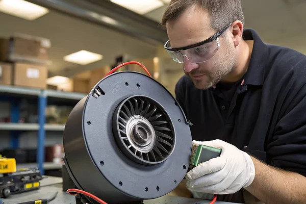
Our DC High-Speed Vortex Blower Fan line is engineered specifically for high static pressure applications -- each design validated on our in-house CFM airflow test system and anechoic noise test chamber as part of our ISO 9001 and IATF 16949 quality process at our Dongguan facility. If your application has a specific system resistance curve or noise constraint, we can discuss the blower design and P-Q characteristics that match it.
FAQ
Is a DC brushless blower fan the same thing as a centrifugal fan?
Yes, in most practical contexts -- "centrifugal fan" describes the aerodynamic architecture (radial impeller, scroll housing), while "DC brushless blower" additionally specifies the motor type. Most modern blower fans intended for electronics or medical applications are both centrifugal in airflow path and brushless in motor commutation.
Can a blower fan be used in a fully open-air application where an axial fan would normally go?
It can, but it's rarely the right choice. Blowers are optimized to generate pressure and deliver concentrated, directed airflow -- in a genuinely open, unrestricted application, an axial fan will typically move more total air volume at lower cost and noise for the same power input.
How does PWM speed control work on a DC brushless blower?
PWM (pulse-width modulation) varies the duty cycle of the voltage signal to the motor driver, which adjusts average power delivery and therefore rotational speed. Most DC brushless blowers accept either a PWM control signal on a dedicated pin or an analog voltage input, depending on the driver circuit design -- the datasheet will specify which control interface the blower supports.
What causes a DC brushless blower to fail over time if brushes aren't the issue?
The primary long-term failure modes in brushless blowers are bearing wear (both ball bearings and sleeve bearings degrade over time under load), impeller imbalance (from contamination or physical damage), and driver electronics failure. Bearing wear is typically the life-limiting factor under normal operating conditions.
Does blower orientation matter -- can it be mounted in any direction?
Orientation can affect bearing lubrication distribution and, in some designs, impeller dynamic balance under gravity loading. Manufacturers specify recommended mounting orientations; running a blower outside its specified orientation envelope can accelerate bearing wear and affect airflow delivery. Check the datasheet before assuming free-axis mounting.
Why do blowers tend to be louder than axial fans at the same airflow output?
Blowers often generate more noise because the centrifugal impeller and scroll housing create more complex turbulence patterns than a simple axial blade, and the concentrated single-outlet geometry can produce tonal noise at blade-pass frequencies. That said, in high-resistance applications where an axial fan would stall noisily or run at extreme RPM to compensate, a correctly sized blower is frequently quieter under actual operating conditions.
How do I read a P-Q curve to find my blower's actual operating point?
Plot your system's resistance curve -- airflow versus pressure drop, estimated from your filter, duct, and heat exchanger losses -- on the same graph as the blower's P-Q curve. The intersection point of the two curves is the operating point: the actual airflow and static pressure the blower will deliver in your system. If that intersection point doesn't meet your thermal requirements, you need either a higher-performing blower or a lower-resistance system design.
DC brushless blowers solve a specific problem -- sustained airflow against real back-pressure -- that axial fans handle poorly and that peak-spec comparisons consistently underestimate. Getting the architecture right starts with characterizing what the system actually demands. Herays has designed and manufactured DC cooling fans and blowers from our Dongguan facility for over 20 years, certified to ISO 9001, ISO 14001, QC 080000, and IATF 16949 -- if your application has a specific pressure, noise, or control requirement, we're glad to work through the P-Q tradeoffs with you.
P-Q curve is the graphical relationship between static pressure and airflow volume a fan produces, measured across its full operating range from free-air delivery to maximum static pressure. It is the primary tool for predicting real-world fan performance at a specific system operating point rather than at the datasheet's peak conditions. ↩
Brushless DC motor is an electric motor that uses electronic commutation through Hall-effect sensors and a driver circuit rather than physical brush-commutator contact to deliver current to motor windings. The absence of sliding contact eliminates the primary progressive wear mechanism of brushed motors, significantly extending operational service life in duty-cycle-intensive applications. ↩

Liang
I've been working with DC fans for 30 years — long enough to have seen the industry evolve from basic sleeve bearing designs to today's high-efficiency, IP68-rated systems built for the harshest environments imaginable. I founded Herays because I believed manufacturers and engineers deserved a supplier who could talk technical from day one. Not just hand over a datasheet, but actually help you select the right fan for your thermal load, your enclosure, your certification requirements. Most of what I write here comes directly from problems I've solved on the factory floor or in customer applications — medical devices, laser equipment, industrial automation, you name it. If it involves moving air efficiently and reliably, I've probably spent time thinking about it. When I'm not obsessing over airflow curves, I'm usually helping a customer figure out why their cooling system isn't performing the way their simulation said it would.
View all posts by Liang