Standard fans fail quietly -- airflow numbers look fine on paper, temperatures keep climbing in the actual system, and the culprit is almost always a pressure problem that a higher CFM rating alone won't fix.
A high-pressure DC blower is the right choice when the airflow path through a system creates enough resistance that a standard axial fan's static pressure capability is exhausted before meaningful airflow reaches the components that need cooling -- which happens more often, and earlier in system design, than most engineers expect.
- Restrictive airflow paths -- dense filters, narrow ducts, packed enclosures -- consume static pressure that a standard axial fan simply doesn't have enough of to push through effectively.
- CFM ratings measured in free air tell you almost nothing about how a fan will actually perform inside a system with real resistance; static pressure ratings and P-Q curves tell you far more.
- Specific symptoms reliably signal a pressure mismatch: inadequate cooling despite seemingly sufficient airflow, fans spinning fast but delivering little perceived airflow at outlets, or performance that degrades sharply as filters load with dust.
- High-pressure DC blowers solve this by generating significantly higher static pressure through centrifugal action, at the cost of more noise, higher power draw, and usually a larger footprint than an equivalently-rated axial fan.
- The tradeoffs are real and worth understanding upfront -- blowers aren't universally better, just better matched to high-resistance applications where axial fans structurally cannot deliver adequate pressure.
Understanding when a system actually needs a blower -- versus when an axial fan is being blamed for a problem that's really an airflow path design issue -- is the practical starting point.
Table of Contents
What Actually Counts as a Restrictive Airflow Path?
Not every enclosed space qualifies, and misidentifying the problem leads to specifying the wrong solution.
A restrictive airflow path is any airflow route where the cumulative resistance of filters, ducts, bends, heat exchangers, or component density creates enough back-pressure to significantly reduce airflow below free-air levels -- typically identifiable by the path's position on a fan's P-Q curve, not by visual inspection alone.
How Resistance Accumulates Through a System
Resistance builds through a system the way friction builds in a pipe -- every element adds to the total back-pressure the fan must overcome. A single dust filter in clean condition might add modest resistance on its own, but a filter in series with a narrow duct, two 90-degree bends, and a tightly packed heatsink array can accumulate resistance that puts the operating point well into the steep part of a fan's P-Q curve1, where airflow falls sharply per unit of added resistance.
The practical categories of restrictive paths worth recognizing:
| Airflow Path Feature | Why It Adds Resistance |
|---|---|
| Fine particulate filters (HEPA-class) | High media density creates significant pressure drop even when clean |
| Narrow or long duct runs | Wall friction and flow velocity compound over length |
| Multiple directional changes | Each bend disrupts laminar flow and adds turbulence-related loss |
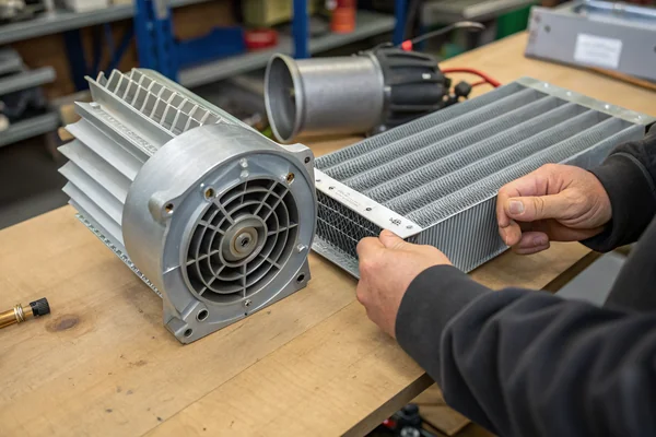
| Dense heat exchanger fins | Fin spacing and depth create high internal resistance |
| Tightly packed component enclosures | Components acting as baffles restrict airflow cross-section |
A system with two or more of these features operating in series is almost always in blower territory rather than axial fan territory, particularly if the operating environment means filters will load with particulate over time -- which reliably increases resistance above the clean-filter baseline.
Static Pressure vs. CFM: What the Numbers Actually Mean Inside a Real System
Free-air CFM ratings are nearly useless for specifying a fan in a resistive system.
CFM ratings measured at zero static pressure describe what a fan can move through open air with no resistance -- the moment any real back-pressure exists in the system, actual delivered airflow drops below that number by an amount determined by the fan's P-Q curve, which is the spec that actually matters for real application performance.
Why P-Q Curves Contain the Information You Actually Need
The ANSI/AMCA Standard 2102 laboratory methodology defines how fan performance is measured across the full range from free-air delivery to shutoff pressure -- the result is the P-Q curve, which plots airflow volume against static pressure from maximum CFM at zero resistance through to maximum pressure at zero airflow. A fan's real operating point inside a system sits wherever the system's resistance curve intersects the fan's P-Q curve.
This matters practically because two fans with the same free-air CFM rating can have dramatically different P-Q curves. A high-CFM axial fan optimized for open-air delivery might reach shutoff pressure at 5–8 mm H₂O and deliver nearly no airflow when the system's operating resistance exceeds that. A blower with similar or even lower free-air CFM might sustain meaningful airflow delivery at 30–60 mm H₂O of system resistance -- a completely different capability profile suited to completely different applications.
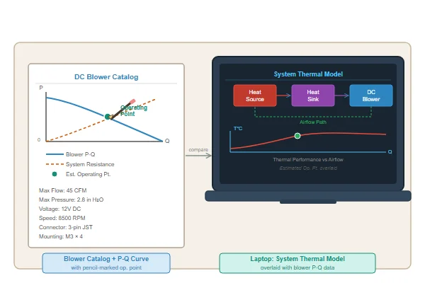
The design exercise, then, is estimating total system resistance at the expected operating point and overlaying it against candidate fans' P-Q curves to verify that the intersection point actually delivers adequate cooling airflow. Selecting by free-air CFM alone skips this entirely and reliably produces thermal failures in restrictive systems.
What Specific Symptoms Signal That an Axial Fan Isn't Delivering Enough Pressure?
The failure mode has recognizable patterns, and catching them early avoids thermal damage.
Signs that a system has exceeded an axial fan's static pressure capability include components running hotter than thermal calculations predicted, minimal perceptible airflow at outlet grilles despite fans running at full speed, and cooling performance that degrades significantly as filters age and load -- all pointing to a pressure mismatch rather than an airflow volume shortfall.
Recognizing the Pattern Before Thermal Damage Occurs
The diagnostic frustration with pressure mismatches is that the fans appear to be working -- they're spinning, they're drawing rated power, they're generating audible airflow noise. The failure is invisible until a thermal sensor or a component failure reveals that actual airflow reaching critical components is a fraction of what the fan's free-air spec suggested.
Specific patterns worth recognizing:
A system where outlet airflow is barely perceptible by hand despite fans running at full speed is almost always pressure-limited -- the fan is consuming its static pressure budget fighting the restriction rather than delivering airflow at the outlet. In an adequate-pressure system, outlet airflow should be clearly perceptible at any meaningful fan speed.
Cooling performance that was adequate when the system was new but degrades noticeably after several months of operation, without any other change to the system, typically reflects a clean-filter operating point that was already marginal, pushed into inadequate territory as filter loading increased system resistance.
Thermal calculations that predicted adequate cooling but real-world temperatures consistently run 10–20°C above model predictions often indicate that the modeled airflow was based on free-air CFM rather than the actual delivered airflow at the real operating point on the P-Q curve.
How High-Pressure DC Blowers Generate the Pressure Axial Fans Structurally Cannot
The mechanism is fundamentally different, not just incrementally better.
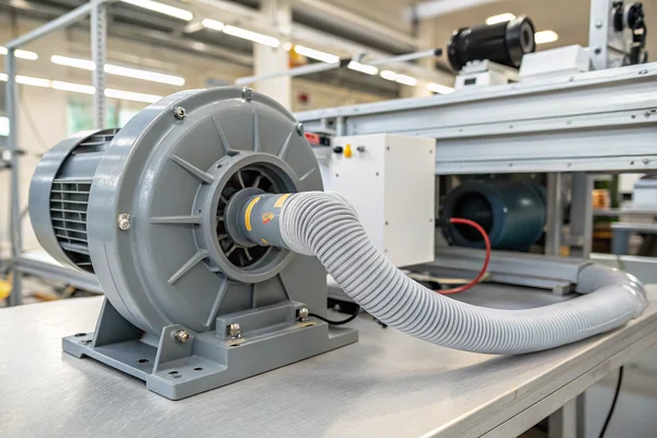
High-pressure DC blowers generate elevated static pressure through centrifugal action -- air enters axially at the impeller hub and is accelerated radially outward by the spinning impeller, exiting perpendicular to the intake -- which converts rotational velocity into pressure far more effectively than axial fans, which push air parallel to their rotation axis and are inherently limited in pressure generation by blade geometry alone.
The Centrifugal Mechanism Explained Without the Aerodynamics Textbook
An axial fan works by angling blades to push air in the direction of the rotation axis -- the same basic principle as a propeller. This works efficiently in open air or low-resistance paths, but the pressure it can generate is directly limited by blade pitch and rotational speed in ways that become impractical to overcome at high resistance.
A centrifugal blower works differently: air is drawn in at the center of a rotating impeller and flung outward by centrifugal force, building velocity along the impeller radius. That velocity converts to pressure at the scroll housing outlet. Because the pressure-building mechanism is the full radial acceleration of the impeller rather than a single blade-pass push, centrifugal blowers can sustain meaningful airflow delivery at static pressures that would stall an axial fan entirely.
| Characteristic | Axial Fan | High-Pressure DC Blower |
|---|---|---|
| Air movement direction | Parallel to rotation axis | Radial (perpendicular to axis) |
| Peak static pressure (typical small DC) | 5–15 mm H₂O | 30–100+ mm H₂O |
| Best-fit applications | Open air, low resistance paths | Filtered, ducted, dense-component systems |
| Footprint for equivalent pressure | Smaller | Larger, or taller |
| Noise profile at equivalent airflow | Generally lower | Generally higher |
The practical implication is that switching from an axial fan to a blower in a high-resistance system isn't just a quantitative upgrade -- it's accessing a different region of the pressure-airflow design space that axial fans structurally cannot reach.
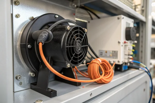
What Are the Real Tradeoffs in Noise, Power, and Cost When Choosing a Blower?
Blowers aren't better -- they're better matched, and the mismatch in the wrong direction has costs too.
High-pressure DC blowers typically draw more power, generate more noise, and carry higher unit costs than axial fans of comparable size -- tradeoffs that are entirely acceptable when the application genuinely requires the pressure capability, but that add avoidable cost and complexity when the system's actual resistance would have allowed an axial fan to perform adequately.
Understanding Each Tradeoff in Practical Terms
Noise is the most immediately noticeable cost. Centrifugal blowers at high speed generate tonal noise from the blade-pass frequency of the impeller interacting with the scroll housing, in addition to broadband turbulence noise, and this tends to be more perceptible as a pitch-modulated whine compared to the lower-register hum typical of axial fans. Applications with strict acoustic requirements need to account for this from the start, since adding acoustic mitigation after the fact is usually inefficient.
Power draw is higher at equivalent airflow for most blower-versus-axial comparisons, though the comparison becomes more nuanced in high-resistance systems where the axial fan is operating at a poor efficiency point on its P-Q curve -- a blower operating near its design point can actually be more efficient than an axial fan struggling against a restrictive path. The efficiency crossover point depends on actual system resistance.
Cost involves both unit price and installation footprint. Blowers typically carry higher unit costs than comparable-output axial fans, and their scroll housing geometry often requires different mounting provisions and outlet duct connection approaches, adding to integration effort. The practical advice is to confirm the system genuinely requires blower-level pressure before committing to the platform, not to default to a blower because "it's more powerful."
Our DC High-Speed Vortex Blower Fan line is engineered for exactly this class of application -- high-resistance paths where axial fan pressure capability runs out before adequate airflow is delivered. Every blower we ship is validated on our in-house CFM airflow test system and anechoic noise test chamber at our Dongguan facility, giving you actual P-Q curve data rather than catalog estimates. If you have a system resistance estimate and a cooling target, we can map candidate blowers against your operating point directly.
How Should You Source and Specify a High-Pressure Blower Without Getting the Operating Point Wrong?
Specifying a blower correctly requires more information than specifying a standard axial fan.
Sourcing a high-pressure DC blower requires knowing the system's estimated operating resistance -- not just the cooling airflow target -- so that the blower's P-Q curve can be matched to the actual operating point rather than to a free-air CFM number that tells you nothing about in-system performance.
The Minimum Specification Inputs Worth Gathering Before Talking to a Supplier
The information needed to specify a blower correctly is more demanding than for an axial fan, but it's the same information a good thermal model requires anyway. Three inputs matter most:
Required airflow at the target components (not at the fan inlet -- at the point where air is actually needed for cooling), expressed in CFM or m³/h. This differs from the fan's free-air delivery by the amount the system resistance consumes.
Estimated total system resistance at operating conditions, expressed in mm H₂O or Pa. This doesn't need to be exact to be useful -- a reasonable estimate of the major resistance contributors (filter drop, duct geometry, component density) produces an operating point range that can be matched to a candidate P-Q curve with enough margin to absorb estimation error.
Constraint envelope: available voltage (12 V, 24 V, 48 V DC are the most common for blower applications), acceptable noise limit if the application has an acoustic specification, physical envelope for the blower and its scroll housing, and any connector or mounting requirements.
With these inputs, a supplier with real P-Q test data can overlay your system resistance estimate against the candidate blower's curve and confirm whether the operating point falls in a region that delivers adequate airflow with reasonable efficiency margin -- a conversation that's much more productive than comparing free-air CFM numbers in a catalog.
FAQ
What voltage options are typically available for high-pressure DC blowers?
12 V and 24 V are the most common for smaller blowers; 48 V options exist for higher-power industrial applications. The voltage available in the system largely determines which blowers are viable without additional power conversion.
Is a blower always louder than an axial fan at the same airflow delivery?
In free-air comparisons, yes, typically. But in high-resistance systems where an axial fan is operating far off its efficiency peak, the acoustic comparison becomes closer -- the axial fan may be running faster than its design speed trying to compensate, while the blower operates near its design point.
Can a high-pressure blower be run at reduced speed to lower noise?
Yes, and this is a common application strategy -- blowers spec'd with headroom above the minimum required operating point can run at reduced PWM duty cycle or reduced voltage to lower both noise and power draw while still delivering adequate airflow for the application's actual thermal load.
How often do filters need to be accounted for in system resistance estimates?
Always, if the system uses filters. And estimates should use a loaded-filter resistance value rather than clean-filter, since the actual operating life of the system includes both. Designing to the clean-filter operating point and accepting degraded performance as filters age is a common source of field thermal problems.
What's the difference between a vortex blower and a standard centrifugal blower?
Vortex blowers (also called regenerative blowers or ring compressors) use a different impeller geometry that recirculates air through the blade path multiple times per rotation, achieving higher pressure ratios than single-pass centrifugal designs at the cost of lower efficiency and higher noise. They occupy a niche between standard centrifugal blowers and compressors in the pressure-versus-flow design space.
Do DC blowers require special thermal management for the motor compared to axial fans?
Blower motors tend to run warmer than axial fan motors at equivalent power because the scroll housing geometry doesn't naturally direct airflow across the motor body the way an axial fan does. This is worth confirming with the supplier for high-ambient-temperature applications.
Choosing between a standard axial fan and a high-pressure blower comes down to one question: does the system's actual resistance exceed what the axial fan's P-Q curve can sustain at the required airflow? Get that answer right upfront, and the rest of the specification follows directly. At Herays, our Dongguan facility has built and tested DC blower and axial fan lines for over 20 years under ISO 9001, ISO 14001, and IATF 16949 certification. If you have a system resistance estimate and a cooling target, we're glad to help match the right solution to the actual operating point.
A P-Q curve plots a fan's delivered airflow volume against static pressure from the free-air maximum to the shutoff pressure maximum, defining every operating point in between. It is the primary performance specification for any fan used in a system with real airflow resistance, because it shows actual delivered airflow at a given back-pressure rather than the free-air maximum only. ↩
ANSI/AMCA Standard 210 defines the laboratory test methodology for measuring fan aerodynamic performance across the full P-Q curve range. Ratings derived from this standard provide comparable, reproducible static pressure and airflow data across different manufacturers, making it the basis for meaningful cross-supplier performance comparisons. ↩

Liang
I've been working with DC fans for 30 years — long enough to have seen the industry evolve from basic sleeve bearing designs to today's high-efficiency, IP68-rated systems built for the harshest environments imaginable. I founded Herays because I believed manufacturers and engineers deserved a supplier who could talk technical from day one. Not just hand over a datasheet, but actually help you select the right fan for your thermal load, your enclosure, your certification requirements. Most of what I write here comes directly from problems I've solved on the factory floor or in customer applications — medical devices, laser equipment, industrial automation, you name it. If it involves moving air efficiently and reliably, I've probably spent time thinking about it. When I'm not obsessing over airflow curves, I'm usually helping a customer figure out why their cooling system isn't performing the way their simulation said it would.
View all posts by Liang