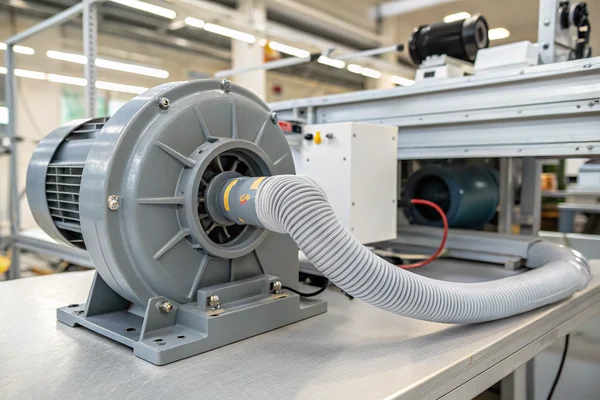
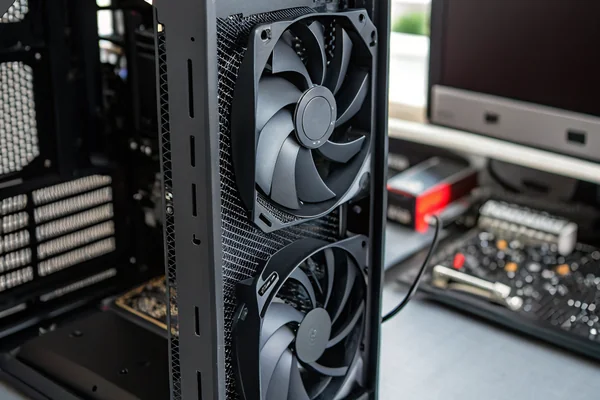
Wrong fan type locked in at the design stage costs time, tooling, and rework. The structural differences between axial fans and blowers are significant enough that swapping one for the other mid-project is rarely painless.
A DC axial fan moves air parallel to its rotational axis and excels at high-volume, low-restriction airflow, while a DC blower moves air perpendicular to its intake and delivers meaningfully higher static pressure -- the right choice depends entirely on whether your application needs to push through resistance or simply move bulk air volume.
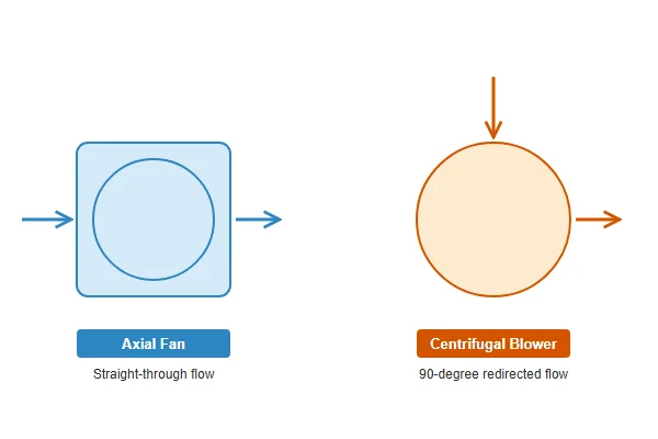
- DC axial fans and DC blowers differ fundamentally in how they move air, not just in shape -- axial fans move air along the rotational axis, blowers redirect it 90 degrees and pressurize it through a volute housing.
- Axial fans win on airflow volume per unit cost and per unit of installed space in open or lightly restricted paths; blowers win on static pressure capability in ducted or restricted paths.
- Size and mounting footprint differ substantially: axial fans fit square cutouts, blowers require clearance for the volute housing and a separate discharge port.
- Neither type is universally superior -- specifying the wrong one will either underperform (axial fan in a high-resistance path) or over-engineer the solution unnecessarily (blower in an open-air cooling bay).
- Cost, lead time, and availability tend to favor axial fans for standard sizes; custom blower configurations can carry longer lead times and higher tooling investment.
Getting this choice right early prevents a common and expensive design mistake. Here's how the two types actually differ, where each one genuinely wins, and what the tradeoffs look like at the procurement stage.
Table of Contents
What Are the Structural Differences That Actually Make These Two Fans Behave Differently?
They look different for a reason, and that reason is function, not aesthetics.
A DC axial fan uses blades mounted on a central hub, spinning to push air straight through along the rotation axis, while a DC blower uses an impeller inside a scroll-shaped volute housing to draw air in axially and discharge it radially -- a fundamentally different mechanical path that produces fundamentally different performance characteristics.
Why the Housing Geometry Is the Real Differentiator
The axial fan's blade-and-ring frame is mechanically simple and optimized for air moving straight through. The blower's volute housing is the critical component: it converts the centrifugal motion of the impeller into pressure by gradually expanding the scroll chamber, slowing the air and building static pressure before it exits the discharge port. This is the same principle used in centrifugal pumps and turbochargers -- geometry converting velocity into pressure.
| Feature | DC Axial Fan | DC Blower |
|---|---|---|
| Air movement direction | Parallel to rotation axis | Intake axial, discharge radial (90°) |
| Housing | Simple frame/ring | Scroll volute with discharge port |
| Impeller type | Blades on open hub | Forward-curved or backward-curved impeller |
| Primary strength | High CFM, low restriction | High static pressure, ducted paths |
| Typical form factor | Square frame, standard mounting | Variable, wider footprint required |
The impeller geometry inside the blower also matters. Forward-curved impellers (more blade curvature in the direction of rotation) tend to generate higher flow at lower pressure, while backward-curved impellers generate more pressure and run more efficiently at higher loads -- a detail worth discussing directly with a supplier when specifying a blower for a demanding application.
How Do the Airflow Directions Differ, and Why Does That Affect System Design?
The discharge direction difference between these two types affects system layout more than most engineers expect until they're routing ducts on a PCB.
An axial fan discharges air in the same direction it was drawn in -- straight through -- making it straightforward to align with linear airflow paths. A blower draws air in axially and discharges it at 90 degrees through a side port, which changes how the fan integrates into the physical layout of the system.
Why 90-Degree Discharge Complicates (and Sometimes Enables) Your Layout
For many systems, a straight-through airflow path is simpler to design around -- an axial fan drops into a cutout and moves air from one face of the enclosure to the other. The blower's perpendicular discharge adds a design constraint: the discharge port needs clearance and needs to align with whatever duct or outlet the system uses. In tight enclosures, that 90-degree turn can be awkward to route around.
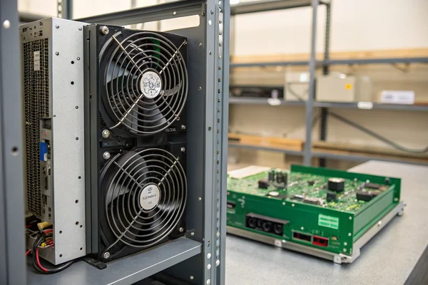
But in certain layouts, it's exactly what's needed. A blower mounted flat against a PCB can draw air from above and discharge it horizontally along the board surface, concentrating airflow across specific hot components in a way an axial fan can't replicate without external ducting. This is a common pattern in laptop cooling systems, compact industrial electronics, and targeted component cooling where an open axial fan would just stir air in the enclosure rather than directing it usefully.
Where Does Static Pressure Performance Actually Separate These Two Types?
Static pressure capability is the clearest performance line between axial fans and blowers, and it's the spec that determines whether a fan can actually move air through your system at all.
A DC blower generates significantly higher static pressure than a comparably sized axial fan, making it the appropriate choice for any application where air must push through meaningful resistance -- dense filter media, heat exchangers, long duct runs, or tightly packed electronics -- while an axial fan's static pressure curve drops off rapidly under restrictive conditions.
Reading the P-Q Curve Tells You More Than Specs Alone
The P-Q curve1 (static pressure vs. airflow curve) is the most important spec for this comparison, and it's measured and validated under ANSI/AMCA Standard 210 laboratory conditions. An axial fan's P-Q curve typically shows strong free-air CFM that drops off steeply as system resistance increases. A blower's curve stays higher at elevated pressure, meaning it maintains meaningful airflow even when the system fights back.
In practical terms: if your system's resistance is effectively zero (open rack, free-air circulation), an axial fan at equivalent wattage almost always delivers more total airflow and does so more efficiently. The moment you add a filter panel, a heat exchanger, or a sealed duct run with length, the blower's pressure capability starts to matter. At high system resistance, an axial fan may be delivering only a fraction of its rated free-air CFM while a blower is still moving useful air volume.
| System Restriction Level | Axial Fan Suitability | Blower Suitability |
|---|---|---|
| Open / near-zero resistance | Excellent | Acceptable, but overkill |
| Light restriction (loose filter) | Good | Good |
| Moderate restriction (heat exchanger) | Marginal | Strong |
| High restriction (dense filter, long duct) | Poor | Best choice |
How Do Size, Cost, and Installation Complexity Compare Between the Two Types?
These are the practical constraints that often drive the final decision as much as aerodynamic theory.
Axial fans win on cost, installation simplicity, and availability in standard sizes -- they drop into a square cutout with four screws and a connector. Blowers cost more for equivalent pressure capability, require more complex mounting that accommodates the volute housing, and carry longer lead times in custom configurations.
Why Axial Fan Standardization Keeps Costs Lower
Axial fans have converged on a small set of standard frame sizes (40mm, 60mm, 80mm, 92mm, 120mm square are the most common) that are compatible across manufacturers and widely stocked. That standardization compresses costs and simplifies sourcing -- a compatible replacement or alternative source is usually available. The installation cutout is a simple square or round opening, and mounting is straightforward.
Blowers are less standardized in form factor. The volute housing shape varies by manufacturer and design, the discharge port location and orientation varies, and the inlet diameter doesn't translate cleanly across product lines the way axial fan frame sizes do. Custom or semi-custom blower configurations for specific applications carry tooling investment and lead times that an equivalent axial fan selection typically avoids.
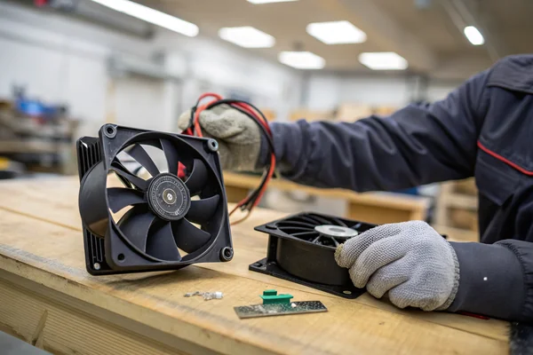
Power draw and noise also differ in ways that interact with installation. Blowers typically draw more power and run at higher noise levels than axial fans delivering equivalent useful airflow in their respective operating ranges. For battery-powered or acoustically sensitive applications, this tradeoff matters and should be modeled explicitly against the system's actual resistance curve rather than assumed.
What Are the Real Failure Modes When You Pick the Wrong Type for the Application?
Choosing the wrong fan type doesn't always cause immediate failure -- sometimes it causes months of thermal drift before anyone connects it to the original selection decision.
Fitting an axial fan into a high-resistance application causes airflow starvation: the fan runs, looks operational, but delivers a fraction of its rated airflow against the system backpressure, leading to gradual thermal overload of components that the cooling system appeared to cover on paper.
Why the Wrong Choice Often Passes Initial Validation
The failure mode is subtle because the fan spins at rated speed and draws rated power -- it doesn't obviously malfunction. The problem is that rated CFM is a free-air spec, and the fan's actual operating point on its P-Q curve, once system resistance is added, may be far below what the thermal model assumed. Component temperatures creep up over time, especially as filter media loads with dust, increasing resistance further. By the time a failure occurs, the original fan selection decision is rarely the first thing investigated.
The reverse failure -- over-specifying a blower in a genuinely open-air application -- is less catastrophic but still costly. The system runs louder than necessary, draws more power than necessary, and costs more than necessary, with no performance benefit that the application actually uses. In battery-powered or acoustically sensitive products, this can push a design out of spec on power budget or noise floor without any obvious single cause.
Specifying correctly requires treating the system resistance curve as a real design input, not an afterthought. Map the P-Q curves of candidate fans against the estimated system resistance before committing to either type.
How Should You Actually Make the Final Selection Decision?
The decision reduces to three questions answered in sequence, not a checklist evaluated all at once.
Determine your system resistance first, then match fan type to it: zero to low resistance points to axial, moderate to high resistance points to blower. If the answer is ambiguous, get P-Q curves for both candidate types and model the actual operating point against your system's resistance estimate before committing.
The Three-Question Decision Sequence
Start with system resistance. If the airflow path is genuinely open -- a ventilation bay with no filter, a simple exhaust opening, a case with significant open area -- axial is almost certainly the right direction. If the path includes any significant restriction, estimate the pressure drop across it.
Second, check whether the airflow direction and physical layout of your enclosure actually accommodates an axial fan. If your layout needs 90-degree discharge to direct airflow across a specific component, that constraint alone may point to a blower regardless of the pressure calculation.
Third, consider size and budget constraints. If the application fits a standard axial frame size, that option is almost always faster to procure and cheaper to replace. If a custom blower housing is required, that cost needs to be modeled against the application's actual requirements to confirm it's genuinely necessary.
| Decision Factor | Points to Axial | Points to Blower |
|---|---|---|
| System resistance | Low (open/lightly restricted) | Moderate to high (filters, ducts, dense components) |
| Airflow direction needed | Straight through | 90-degree discharge required |
| Space / form factor | Standard square cutout available | Blower profile fits layout better |
| Budget / lead time | Cost-sensitive, fast sourcing needed | Application justifies custom housing investment |
| Noise sensitivity | Lower noise priority | Acceptable tradeoff for pressure |
We manufacture both DC axial fans and DC high-speed vortex blower fans from our Dongguan facility, and both product lines are validated on our in-house CFM airflow test system and anechoic noise test chamber under our ISO 9001 and IATF 16949 quality process. When an application sits near the boundary between axial and blower territory -- where the right call isn't obvious from the spec sheet alone -- we can run both options against your system's estimated resistance curve and discuss which P-Q profile actually fits your operating point before you commit to tooling.
FAQ
Can I replace an axial fan with a blower in the same cutout?
Almost certainly not without mechanical modification -- the blower's volute housing has a different footprint and requires a discharge port that an axial fan cutout doesn't provide. Plan for layout changes if switching types mid-project.
How do I estimate my system's resistance if I don't have test data yet?
A rough first pass: sum up the pressure drops across major flow restrictions (filter media typically 0.05–0.2 inches water gauge, heat exchangers vary widely). Fan manufacturers can help map candidate P-Q curves against a reasonable resistance range even before you have measured data.
Do DC blowers run louder than axial fans at equivalent airflow?
Generally yes in most operating conditions -- the higher rotational speeds and the volute discharge dynamics both contribute to elevated noise levels compared to an axial fan delivering equivalent free-air CFM. If acoustic spec is tight, confirm noise levels against your specific operating point, not just free-air ratings.
Is one type more reliable than the other over a long service life?
Both types' reliability centers primarily on bearing quality and motor design rather than fan type. A well-engineered blower with a quality bearing system will outlast a poorly specified axial fan, and vice versa. Service life is better predicted by bearing type, rated speed vs. operating speed, and thermal environment than by axial vs. blower architecture.
Are there applications where neither type is clearly better?
Yes -- lightly restricted applications with moderate CFM requirements sit in a zone where both types can work, and the tie-breaker ends up being installation geometry, noise requirements, or sourcing practicality rather than a clear aerodynamic argument for either side.
Does blade or impeller material affect which type to choose?
It's a secondary factor -- material affects operating temperature range, vibration characteristics, and long-term dimensional stability, but it doesn't change the fundamental axial-vs-blower selection logic. Confirm material specs separately once the fan type decision is made.
Can a DC blower be speed-controlled the same way as an axial fan?
Yes -- most DC blowers support PWM speed control using the same signal standards as DC axial fans. Verify the specific control input and speed range with the supplier, since blowers can have minimum speed requirements below which the volute doesn't pressurize effectively.
Axial fans and blowers solve different problems, and fitting the wrong one into your system creates costs that don't show up until thermal testing or field failures surface them. At Herays, our Dongguan facility has manufactured both DC axial fans and DC blower fans for over 20 years, certified under ISO 9001, ISO 14001, QC 080000, and IATF 16949. If your application sits near the boundary between these two types, we're glad to work through the P-Q curve data with you before the design is locked.
The P-Q curve is a graphical representation of a fan's static pressure output plotted against its volumetric airflow at a given speed. It is the primary tool for matching a fan to a real system because it shows how the fan's output changes as resistance increases, not just its best-case free-air performance. ↩

Liang
I've been working with DC fans for 30 years — long enough to have seen the industry evolve from basic sleeve bearing designs to today's high-efficiency, IP68-rated systems built for the harshest environments imaginable. I founded Herays because I believed manufacturers and engineers deserved a supplier who could talk technical from day one. Not just hand over a datasheet, but actually help you select the right fan for your thermal load, your enclosure, your certification requirements. Most of what I write here comes directly from problems I've solved on the factory floor or in customer applications — medical devices, laser equipment, industrial automation, you name it. If it involves moving air efficiently and reliably, I've probably spent time thinking about it. When I'm not obsessing over airflow curves, I'm usually helping a customer figure out why their cooling system isn't performing the way their simulation said it would.
View all posts by Liang