Guessing at CFM from a similar past project, or trusting a manufacturer's "recommended" fan without checking the math, is how thermal problems get discovered after the design is already committed.
Calculating required CFM starts with your system's actual heat load in watts, applies a standard formula relating heat, temperature rise, and airflow, then checks that figure against your system's real static pressure resistance -- skipping the resistance check is the most common reason a calculated CFM figure doesn't translate into adequate real-world cooling.
- CFM requirements start with an accurate thermal load figure in watts -- everything downstream of this number depends on getting it right.
- The core formula (CFM = heat load / (temperature rise × air density × specific heat), adjusted for unit conventions) converts thermal load and acceptable temperature rise into required airflow.
- System resistance from filters, grilles, and internal components means a fan's free-air CFM rating overstates what it will actually deliver once installed.
- Online CFM calculators can speed up the arithmetic, but only if you provide accurate thermal load and resistance inputs -- the calculator can't fix a wrong input.
- Selecting a fan from your calculated CFM and pressure requirements together, with reasonable margin, is what actually determines correct fan selection.
Working through this calculation deliberately, rather than relying on a rule of thumb from a previous project, is what prevents a system from being undersized in ways that only show up after deployment.
Table of Contents
How Do You Determine What CFM You Actually Need?
This is the foundational question every other step in the calculation depends on answering accurately.
The CFM you actually need depends on your system's total heat dissipation in watts and how much temperature rise above ambient you're willing to accept -- these two numbers, combined through a standard formula, produce your minimum required airflow, which is different from an arbitrary target based on what "seems like enough" for a system of your general size.
Why Generic Size-Based Estimates Fall Short
Two systems of similar physical size can have very different actual heat loads depending on their specific components, meaning a CFM estimate based on enclosure size alone -- rather than actual thermal load -- can be significantly wrong in either direction. Working from your system's real, measured or carefully estimated power dissipation, rather than a generic size-based rule of thumb, is what makes the resulting CFM figure actually meaningful for your specific design.
What's the Actual Formula Converting Heat Load Into CFM?
This formula is the mathematical core of the entire sizing exercise.
The standard formula is CFM = (heat load in watts × 3.16) / temperature rise in degrees Fahrenheit, a commonly used simplified form that bundles air density and specific heat constants into the 3.16 conversion factor for standard sea-level conditions -- for metric calculations, the underlying relationship is airflow = power / (temperature rise × air density × specific heat).
Why the Simplified Constant Only Applies Under Standard Conditions
The 3.16 conversion factor assumes standard sea-level air density and temperature, which means it becomes less accurate at high altitude or unusually hot ambient conditions where air density is meaningfully lower. For most standard applications near sea level, the simplified formula gives a reliable working figure, but for systems operating at significant altitude or in unusually hot environments, using the full formula with an adjusted air density value produces a more accurate result.
| Input | Example Value | Resulting CFM (approx) |
|---|---|---|
| 50W heat load, 10°F rise | 50W, 10°F | ~15.8 CFM |
| 50W heat load, 20°F rise | 50W, 20°F | ~7.9 CFM |
| 100W heat load, 10°F rise | 100W, 10°F | ~31.6 CFM |

Why Does System Resistance and Static Pressure Change the Real-World Number?
The calculated CFM figure is only the beginning -- confirming a fan can actually deliver it against real resistance is the step most often skipped.
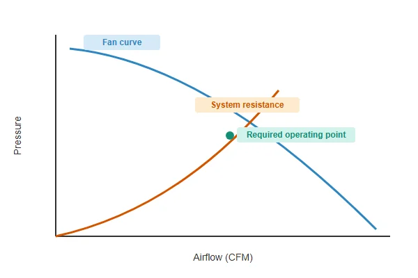
Your calculated CFM figure represents the airflow needed in an unrestricted path, but any filters, grilles, or internal component density in your actual enclosure add static pressure resistance that reduces how much airflow a given fan actually delivers once installed -- meaning you need to check your calculated CFM against the fan's performance at your system's actual estimated resistance, not its free-air rating.
Why Skipping This Step Is the Most Common Sizing Mistake
A fan selected purely by matching its free-air CFM rating to your calculated requirement will often underperform once installed, because free-air ratings don't account for any of the restriction your actual enclosure introduces. Estimating your system's resistance -- from component specs, filter manufacturer data, or direct measurement on a prototype -- and reading the fan's actual delivered CFM at that pressure point from its P-Q curve is what closes this gap between calculated theory and real-world performance.
How Do You Actually Select a Fan From Your CFM and Pressure Requirements?
With both numbers calculated, choosing a specific fan model becomes a matter of matching its P-Q curve to your operating point.
Select a fan whose P-Q curve shows it delivering your required CFM at your estimated system resistance, with a reasonable margin above the bare minimum to account for real-world variables like manufacturing tolerance, aging, and dust accumulation -- a fan barely meeting the calculated minimum with no margin is more likely to become inadequate over the system's service life.
Why Margin Isn't Optional Padding
A fan sized to exactly meet a calculated minimum has no buffer for the fan naturally losing some performance as it ages, gradual dust accumulation restricting airflow between cleanings, or minor manufacturing variance between individual units. A margin of roughly 20-30% above the calculated minimum is a common and reasonable target, keeping the system thermally healthy across realistic variation rather than only under ideal day-one conditions.
Are Online CFM Calculators Actually Reliable, or Should You Do the Math Yourself?
Online tools can speed up the arithmetic, but they carry the same input-quality dependency as manual calculation.
Online CFM calculators are reliable for the arithmetic itself, since they're generally applying the same standard formula discussed here, but they're only as accurate as the thermal load and temperature rise inputs you provide -- a calculator can't correct for an inaccurate heat load estimate, and most online tools don't account for system resistance at all.
Why Understanding the Underlying Formula Still Matters
Relying on a calculator without understanding what it's actually computing makes it harder to sanity-check the output or recognize when an input assumption (like ignoring system resistance) means the calculator's result needs further adjustment before it's actually usable for fan selection. Using a calculator to speed up the CFM arithmetic while still manually accounting for system resistance and margin afterward combines the convenience of automated calculation with the completeness a full sizing process requires.
We help customers validate their CFM calculations against real measured performance, since our published airflow specs are tested on our in-house CFM airflow test system at our Dongguan facility rather than derived from theoretical figures alone. With over 20 years of production experience under ISO 9001 certification, we're glad to review your thermal load and resistance estimates and help confirm the right fan for your calculated requirement.
How Do You Validate a Calculated CFM Requirement Against a Real Prototype?
The calculation gets you a solid starting figure, but confirming it against measured performance closes the loop.
Validate a CFM calculation by measuring actual component temperatures on a working prototype under representative load and comparing them against your target temperature rise -- if measured temperatures run higher than the calculation predicted, either the thermal load estimate, the resistance estimate, or the fan's real delivered airflow diverged from the assumptions used.
Why This Step Catches What Pure Calculation Can Miss
Real systems have airflow paths, component placement, and power draw that don't always match the simplified assumptions a calculation relies on, meaning measured results occasionally diverge from the predicted outcome even with careful inputs. Catching this gap during prototyping, while design changes are still relatively cheap, is far more valuable than discovering an undersized fan after a product has already shipped.

FAQ
What's a reasonable default temperature rise if I don't have a specific component limit?
This varies by application, but many general electronics cooling designs target a rise in the 10-20°F (roughly 5-11°C) range above ambient as a starting point, adjusted based on your most temperature-sensitive component's actual rated limit.
Does the CFM formula change for liquid-cooled or hybrid thermal systems?
The airflow-side calculation for any air-cooling component within a hybrid system follows the same principles, though the total heat load figure needs to account for how much heat the liquid cooling portion is handling separately versus what air cooling needs to manage.
How much does altitude actually affect the calculation in practice?
Air density decreases meaningfully at higher elevations, which can require correspondingly higher CFM to move the same mass of air needed for equivalent cooling -- worth adjusting for installations above roughly 1,000-1,500 meters where the effect becomes more significant.
Is it possible to calculate CFM without knowing exact component power draw?
You can estimate from datasheet typical power figures if exact measurement isn't available, though this introduces more uncertainty into the calculation -- measured power draw under representative conditions gives a more reliable result when available.
Should I calculate CFM per fan or for the whole system?
Calculate total system CFM requirement first, then divide across your planned number of fans if using multiple units, accounting for how multiple fans in parallel or series actually combine airflow and pressure.
How often should I revisit a CFM calculation during a product's development?
Whenever thermal load estimates change meaningfully -- new components, updated power figures, or enclosure design changes affecting resistance -- since the original calculation may no longer reflect the current design.
Calculating required CFM correctly comes down to working through thermal load, the core formula, system resistance, and margin systematically rather than estimating from habit. At Herays, our Dongguan facility validates fan performance specs on real testing equipment so the numbers you calculate against are accurate, backed by over 20 years of experience under ISO 9001 certification. If you're working through a CFM calculation for a specific application, we're glad to help confirm the right fit.

Liang
I've been working with DC fans for 30 years — long enough to have seen the industry evolve from basic sleeve bearing designs to today's high-efficiency, IP68-rated systems built for the harshest environments imaginable. I founded Herays because I believed manufacturers and engineers deserved a supplier who could talk technical from day one. Not just hand over a datasheet, but actually help you select the right fan for your thermal load, your enclosure, your certification requirements. Most of what I write here comes directly from problems I've solved on the factory floor or in customer applications — medical devices, laser equipment, industrial automation, you name it. If it involves moving air efficiently and reliably, I've probably spent time thinking about it. When I'm not obsessing over airflow curves, I'm usually helping a customer figure out why their cooling system isn't performing the way their simulation said it would.
View all posts by Liang