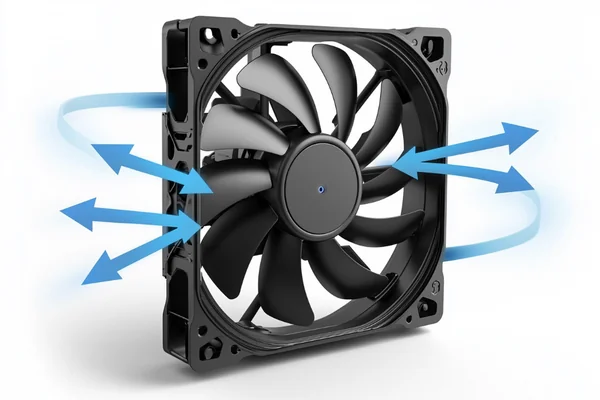
Your fan's datasheet says 100 CFM, but your system is still overheating. You're wondering if the fan is underperforming, but how can you be sure?
You can't accurately measure CFM without a lab-grade air chamber.1 Instead of measuring, you should use the manufacturer's P-Q curve to estimate the fan's performance based on your system's resistance, also known as static pressure. This is the professional approach for selecting the right fan.2
I get this question a lot from engineers and buyers. They want to verify a fan's performance, which makes perfect sense. But trying to measure CFM directly is often the wrong path. It leads to frustration and can result in picking the wrong fan. Let's explore why and what you should do instead.
Why Does Measuring Actual Airflow Matter?
You've designed a system that needs specific cooling. If the airflow is too low, components overheat and fail. Getting it right is critical for reliability and performance.
Measuring or estimating actual airflow is crucial because it confirms your cooling system works as designed. Without enough airflow, components can overheat, leading to performance throttling or permanent damage3. It's the difference between a reliable product and a source of customer complaints.

I’ve seen many projects where a simple cooling miscalculation caused major delays. The goal is to ensure the fan you choose removes heat effectively. Your components have a maximum operating temperature. The fan's job is to move enough air to keep them well below that limit. If the actual airflow is less than required, your device might work on a test bench but fail in the field. This is why we don't just guess. Understanding the real airflow inside your system helps you predict thermal performance, guarantee product longevity, and avoid costly post-launch fixes. It is about risk management for your entire product. You need to be sure that the cooling is adequate not just for today, but for the entire lifespan of the device, even as dust builds up4 and ambient temperatures change.
How to Estimate CFM from Specs Instead of Measuring?
You need a reliable way to predict fan performance, but you don't have an expensive air chamber. How can you use the spec sheet to make an accurate choice?
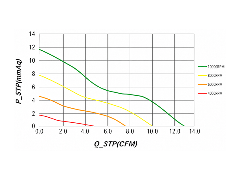
Look for the P-Q (Pressure-Airflow) curve in the fan's datasheet. First, estimate your system's impedance (low, medium, or high). Then, find where your system's impedance curve intersects the fan's P-Q curve. This intersection is your fan's real-world operating point.5
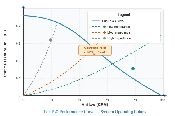
The P-Q curve is your most powerful tool. It plots airflow (CFM) on the X-axis against static pressure on the Y-axis. Every fan has one. Your system also has an impedance curve6, which shows how much pressure is generated as airflow increases. While you can't easily measure this, you can estimate it. An open case with good ventilation has low impedance. A dense server with filters and packed components has high impedance. By overlaying your estimated system impedance on the fan's P-Q curve, you find the actual operating point. This is far more reliable than just looking at the max CFM number.
| Impedance Level | System Characteristics | Fan Choice Strategy |
|---|---|---|
| Low | Open mesh, few obstructions, clear airflow path. | A high airflow (CFM) fan is effective. |
| Medium | Some filters, grills, moderate component density. | Balance of CFM and static pressure needed. |
| High | Dense heatsinks, radiators, narrow paths, 1U servers. | A high static pressure fan is required. |
What is an Anemometer and Why is it Often Misleading?
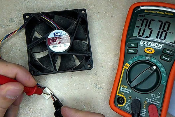
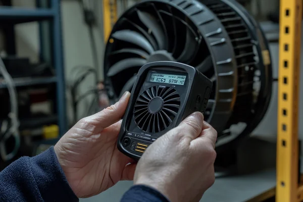
You might think a handheld anemometer is the perfect tool for measuring airflow. Just hold it up to the fan, right? Unfortunately, this simple test can be very deceptive.
An anemometer measures air speed at a single point. To get airflow (CFM), you must multiply speed by the cross-sectional area7. However, airflow from a fan is not uniform; it's turbulent8. A single-point measurement is almost always inaccurate and not representative of total volume.
When I talk to engineers, some mention using an anemometer. I always caution them. The airflow coming off a fan's blades is complex. The speed is highest at the tips and can even be negative near the hub, which is a dead spot. Holding an anemometer in one spot might give you a high reading, while moving it an inch over gives a much lower one. To get a true CFM value, you would need to take dozens of measurements across the entire fan outlet and average them—a process called traversing9. This is tedious and still prone to error without a proper test duct to straighten the airflow. It’s simply not a practical or reliable method for qualifying a fan for your system. It gives a false sense of precision when the reality is much more complicated.
How Do Ducts and Obstructions Affect Airflow?
You picked a fan with great specs, but inside your device, it feels like it's barely moving any air. What's killing your fan's performance?
Every object in the airflow path creates resistance, or static pressure. Grills, filters, heatsinks, cables, and even sharp turns in a duct force the fan to work harder. As static pressure increases, the actual airflow (CFM) delivered by the fan decreases significantly.
Think of it like this: your fan is a tiny engine trying to push air through a maze. The "free air" CFM rating is what the fan can do with no maze at all. Now, add a finger guard. That's a small obstacle that creates a little static pressure. Add a dust filter. That's a bigger obstacle and more pressure. Now push that air through a dense heatsink. That's a huge wall of resistance. Each of these elements adds to the total system impedance. A fan designed for high airflow but low static pressure will see its performance plummet in a restrictive environment. This is why high-speed blower fans exist—they are built to overcome high static pressure in tight spaces, even if their "free air" CFM isn't the highest. They generate a more forceful, directed airstream.
What is the Difference Between Free Air CFM and System CFM?
The fan's box proudly advertises 120 CFM, but you know you're not getting that. Is the number a lie, or is there something you're missing?
Free Air CFM is a fan's maximum potential, measured in an open lab environment with zero resistance. System CFM is the actual airflow you get when the fan is installed in your device, fighting against real-world static pressure from filters, grills, and components.
This is the single most common point of confusion I see. The Free Air CFM is a standardized benchmark. It tells you the fan's absolute maximum output under ideal, unrealistic conditions. It's useful for comparing one fan's motor and blade design to another's at a basic level. However, your system will never be a "free air" environment. The moment you put a screw or a grill in front of the fan, you introduce static pressure, and the airflow drops. The real performance, or System CFM, is always lower. The P-Q curve perfectly illustrates this relationship: when static pressure (Y-axis) is zero, airflow (X-axis) is at its maximum (Free Air CFM). As pressure rises, airflow falls. Your job is to find a fan that still provides enough airflow at your system's specific pressure level.
Conclusion
Stop trying to measure CFM. Instead, learn to read a fan's P-Q curve and estimate your system's impedance. This ensures you choose a fan that works effectively.
"[PDF] Fans and Blowers Test Procedure NOPR: Public Meeting", https://downloads.regulations.gov/EERE-2021-BT-TP-0021-0015/content.pdf. A source from an organization like the Air Movement and Control Association (AMCA) can describe Standard 210, which specifies the use of a dual-chamber apparatus to create uniform, measurable conditions for determining fan airflow performance, as direct measurement in non-ideal environments is unreliable. Evidence role: mechanism; source type: institution. Supports: The standard method for testing fan performance to determine its CFM rating.. ↩
"Fan Engineering Guide - Chicago Blower", https://www.chicagoblower.com/resources/fan-engineering-guide. An engineering design guide or textbook can confirm that the standard method for fan selection involves matching the fan's pressure-flow (P-Q) performance curve with the system's impedance curve to find the actual operating point, ensuring adequate airflow under real-world conditions. Evidence role: expert_consensus; source type: education. Supports: The standard engineering practice for selecting a [fan for a](https://herays.com/case_study/high-speed-dc-blower-fan-compact-3d-printer-cooling-module/) specific application.. ↩
"Dynamic frequency scaling", https://en.wikipedia.org/wiki/Dynamic_frequency_scaling. A technical paper or article can explain that thermal throttling is a self-preservation mechanism in processors where the clock speed and voltage are automatically reduced to decrease heat generation when temperatures exceed a predefined threshold, thus preventing permanent damage. Evidence role: mechanism; source type: research. Supports: The mechanism by which excessive heat leads to performance reduction in electronic components.. ↩
"Impact of dust and temperature on photovoltaic panel ... - PMC", https://pmc.ncbi.nlm.nih.gov/articles/PMC11379991/. Research studies have shown that the accumulation of dust on heatsinks and fan blades can significantly increase thermal resistance and impede airflow, leading to higher component operating temperatures over time. Some studies quantify this performance degradation in relation to dust layer thickness. Evidence role: statistic; source type: paper. Supports: The impact of dust accumulation on the thermal performance of cooling systems.. ↩
"An Engineer's Guide to Understanding Fan Curves - Q-PAC", https://www.q-pac.com/resources/engineers-guide-to-understanding-fan-curves. An engineering resource on fluid dynamics or thermal management can confirm that a fan's actual performance point in a given system is determined by the intersection of the fan's characteristic P-Q curve and the system's impedance curve. This point represents the equilibrium where the pressure generated by the fan matches the pressure loss of the system for a given flow rate. Evidence role: mechanism; source type: education. Supports: The method for determining a fan's actual performance in a system.. ↩
"[DOC] Fan Configuration and Airflow Impedance", https://www.sjsu.edu/people/nicole.okamoto/courses/me_146/Fan%20Configuration%20and%20Airflow%20Impedance%20Lab%20Manual%20Part%201%20%20ME146.doc. A technical guide can define the system impedance curve (or system resistance curve) as a graphical representation of the pressure drop across a system as a function of the airflow rate. The pressure loss is generally proportional to the square of the flow velocity, resulting in a parabolic curve. Evidence role: definition; source type: encyclopedia. Supports: The definition and characteristics of a system impedance curve in the context of fluid flow.. ↩
"Volumetric flow rate", https://en.wikipedia.org/wiki/Volumetric_flow_rate. A source on physics or fluid dynamics can provide the formula for volumetric flow rate (Q), which is calculated as the product of the average fluid velocity (v) and the cross-sectional area (A) through which the fluid is flowing (Q = v × A). Evidence role: definition; source type: encyclopedia. Supports: The physical formula for calculating volumetric flow rate.. ↩
"[Axial fan](https://herays.com/12v-vs-24v-vs-48v-dc-axial-fan/) design - Wikipedia", https://en.wikipedia.org/wiki/Axial_fan_design. Aerodynamic studies and fluid dynamics texts explain that the airflow exiting an axial fan is highly complex, characterized by a non-uniform velocity profile (with lower velocity near the hub and tips), swirl, and turbulence generated by the rotating blades passing through the air. Evidence role: mechanism; source type: paper. Supports: The non-uniform and turbulent nature of the airflow produced by an axial fan.. ↩
"Performing a Duct Traverse - YouTube",
. A source such as an ASHRAE (American Society of Heating, Refrigerating and Air-Conditioning Engineers) standard or a measurement handbook can define the traverse method, which involves taking multiple air velocity readings at specified points across the cross-section of a duct to calculate an average velocity, which is then used to determine the total volumetric flow rate. Evidence role: definition; source type: institution. Supports: The definition and procedure of the traversing method for measuring airflow.. ↩
Liang
I've been working with DC fans for 30 years — long enough to have seen the industry evolve from basic sleeve bearing designs to today's high-efficiency, IP68-rated systems built for the harshest environments imaginable. I founded Herays because I believed manufacturers and engineers deserved a supplier who could talk technical from day one. Not just hand over a datasheet, but actually help you select the right fan for your thermal load, your enclosure, your certification requirements. Most of what I write here comes directly from problems I've solved on the factory floor or in customer applications — medical devices, laser equipment, industrial automation, you name it. If it involves moving air efficiently and reliably, I've probably spent time thinking about it. When I'm not obsessing over airflow curves, I'm usually helping a customer figure out why their cooling system isn't performing the way their simulation said it would.
View all posts by Liang