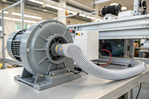
Picking the wrong control method for a DC brushless blower doesn't just leave performance on the table -- it can cause unstable operation, premature motor wear, and thermal runaway in the system it was supposed to protect.
DC brushless blower control methods -- PWM, direct voltage adjustment, and closed-loop tachometer feedback -- each suit different application requirements. PWM offers the most precise speed control with minimal thermal loss, voltage adjustment is simpler but less efficient at low speeds, and tachometer feedback adds closed-loop stability where speed accuracy under variable load genuinely matters.
- DC brushless blowers behave differently from axial fans under control inputs due to their higher static pressure output and steeper torque-speed characteristics, making control method selection more consequential.
- PWM control varies duty cycle to set blower speed with high efficiency and minimal heat dissipation in the control circuit, and is the most common method for precision applications.
- Direct voltage control is simpler to implement but wastes energy as heat at reduced speeds and can cause instability near the motor's minimum operating voltage.
- Tachometer (tach) feedback enables closed-loop speed regulation, compensating for load changes automatically -- essential when backpressure varies or consistent airflow targets must be maintained.
- Control method selection depends on how much the operating load varies, how tight the speed or airflow tolerance needs to be, and what the system's power budget actually allows.
The right control method for a DC brushless blower follows directly from what the application actually demands -- and understanding why blowers differ from axial fans is the right place to start.
Table of Contents
Why Blower Control Isn't the Same Problem as Axial Fan Control
Assuming a control approach that works well on an axial fan will transfer cleanly to a blower is a common and consequential mistake.
DC brushless blowers operate at much higher static pressures and have steeper torque-speed curves than typical axial fans, which means small changes in control input produce larger, less predictable changes in actual operating point -- and the consequences of poor control (stall, surge, or excessive noise) are more severe.
Why the Blower's Operating Curve Changes Everything
An axial fan running in a lightly restricted duct stays close to its free-air CFM even when speed drops modestly. A centrifugal blower, by contrast, is designed to push against real resistance -- filters, ductwork, enclosed housings -- and its pressure-flow curve is far steeper. Drop the speed too far and the blower can stall against its own backpressure, dropping airflow dramatically rather than proportionally. This non-linearity means the control system has to be matched to the blower's actual operating range rather than just wired up and left to whatever happens.
Beyond the curve shape, brushless blower motors also draw meaningfully more current than equivalently-sized axial fan motors at operating speed, since they're doing more mechanical work per rotation. Control circuitry that's undersized for that current will either throttle performance or fail early. And because many blower applications involve enclosed housings with limited natural convection, thermal management of both the motor and the control circuit becomes a genuine design constraint rather than an afterthought.
| Characteristic | DC Axial Fan | DC Brushless Blower |
|---|---|---|
| Typical static pressure range | Low | High |
| Torque-speed curve slope | Gradual | Steep |
| Sensitivity to control input | Moderate | Higher |
| Stall risk at low speed | Low | Real concern |
| Current draw | Lower | Higher |
PWM Control: Why It's the Default Choice for Most Precision Blower Applications
PWM isn't the most common blower control method by accident -- it genuinely handles the blower's operating characteristics better than most alternatives.
PWM (Pulse Width Modulation)1 controls blower speed by rapidly switching the supply voltage on and off at a fixed frequency, varying the duty cycle to set average power delivery -- this keeps the control switch either fully on or fully off at all times, nearly eliminating resistive heat loss in the control circuit while providing precise, repeatable speed adjustment.
How PWM Interacts With a Blower's Internal Drive Electronics
Most DC brushless blowers have onboard motor drive electronics that interpret the PWM signal and manage commutation internally, which means the PWM input is a speed command signal rather than a raw power switch. This architecture puts the burden of current management on the blower's own drive circuitry, simplifying the external control design considerably. The typical PWM frequency for blower control ranges from roughly 1 kHz to 25 kHz, with higher frequencies generally reducing audible switching noise at the cost of slightly higher switching losses in the drive transistors.
One practical detail worth knowing: the minimum duty cycle at which a given blower will still spin reliably varies by design and needs to be validated in the actual application, not assumed from the datasheet. Some blowers stall or behave erratically below 20-30% duty cycle, particularly under backpressure. If the application needs true low-speed operation, confirming the blower's minimum stable PWM duty cycle under representative load conditions is a step that pays off in commissioning.
PWM Frequency and Acoustic Noise Tradeoff
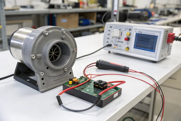
If audible noise from the control signal itself is a concern -- common in medical, laboratory, or office-deployed equipment -- PWM frequency should be set above the human hearing range (above ~20 kHz). Below that threshold, the switching frequency can manifest as a faint but perceptible whine layered on top of the blower's normal operating noise, which is fixable at the design stage but annoying to discover during final product validation.
Simple Voltage Control: Where It Works and Where It Doesn't
Voltage control looks attractive because of its simplicity -- but that simplicity has a real cost at the operating points that matter most.
Adjusting supply voltage directly varies blower speed by changing the average power delivered to the motor, but at reduced voltages the control circuit dissipates the difference as heat rather than delivering it to the motor -- making voltage control less efficient at partial speed and potentially unstable near minimum operating voltage.
Why Efficiency Degrades Quickly at Partial Speed
In a simple linear regulator-based voltage control scheme, the regulator sits between supply and motor and absorbs the voltage difference as heat. At 50% speed (roughly 50% voltage), a meaningful fraction of the input power is being turned into heat in the control circuit rather than useful airflow. For applications that run at reduced speed for significant periods -- which describes most thermal management applications -- this is a real power budget and thermal management concern, not a theoretical one.
Resistive voltage dividers are even simpler but share the same fundamental problem: they waste power continuously, their output voltage varies with load (motor current), and they provide no inherent stability against backpressure changes. The practical result is a blower speed that wanders as system resistance changes, which may be acceptable in very simple, lightly loaded applications but fails quickly in anything more demanding.
Where voltage control remains genuinely useful is in low-cost, fixed-operating-point applications where the blower runs at a single predetermined speed and cost and component count matter more than efficiency -- think simple exhaust fans in budget equipment with stable, known thermal loads.
Tachometer Feedback: When and Why You Actually Need Closed-Loop Control
Open-loop control -- whether PWM or voltage -- sets a command and hopes the blower delivers it. Closed-loop control confirms it did.
Tachometer feedback allows the control system to measure actual blower speed in real time and continuously correct the control signal to maintain a target speed, compensating automatically for load changes, supply voltage variation, and motor aging -- making it the right choice when consistent airflow performance matters more than simplicity.
How Tach Signals Work in Practice
Most DC brushless blowers with tach output generate a simple digital pulse train, typically two pulses per motor revolution, on a dedicated signal wire. The control system measures pulse frequency, calculates actual RPM, and compares it to the setpoint. If the blower is running slow -- because backpressure increased, voltage drooped, or the motor is warming up -- the controller increases the PWM duty cycle or supply voltage to compensate. If it's running fast, it reduces the command. This feedback loop runs continuously, keeping the blower on target within the control system's response bandwidth.
The practical design question is how tight the speed tolerance needs to be and how fast load changes occur. A blower driving a consistently loaded duct system doesn't need aggressive closed-loop gains, and a slow integrating control loop is enough to hold speed within a few percent. A blower managing airflow in a system where filters load up progressively, or where a valve changes state suddenly, needs faster loop response and tighter gain tuning to avoid significant transient speed errors.
Alarm Output as a Minimum Viable Feedback Signal
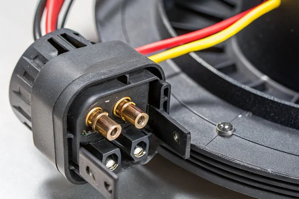
Even if a full closed-loop control architecture isn't justified, a blower with a tach output enables something simpler but genuinely valuable: a locked-rotor or stall alarm. If the tach signal stops pulsing when the blower is supposed to be running, the system knows to trigger a fault response -- a warning light, a shutdown, a notification to maintenance. This is inexpensive to implement and catches a failure mode (blower stall or failure) that open-loop control is completely blind to.
How to Actually Choose Between PWM, Voltage, and Closed-Loop for Your Application
The right control method isn't universal -- it's the one that fits what the application actually demands at the lowest added complexity that still meets the requirement.
Choosing a blower control method starts by answering three questions: how much does operating backpressure vary, how tightly does airflow or speed need to be maintained, and what is the actual power budget at partial-speed operation? The answers to those three questions reliably point to PWM, voltage, or closed-loop as the right architecture.
A Decision Framework That Holds Up in Practice
If backpressure is stable and low, speed tolerance is loose, and cost is paramount, direct voltage control at a fixed operating point is defensible. If backpressure is moderate and varies predictably, and speed needs to be settable but doesn't need to self-correct, open-loop PWM is the standard choice and handles most DC brushless blower applications. If backpressure varies unpredictably (loading filters, variable duct configurations, multiple operating modes), or if consistent airflow must be maintained within a tight tolerance regardless of load, closed-loop tach feedback is necessary rather than optional.
| Application Characteristic | Recommended Control Method |
|---|---|
| Fixed speed, stable load, cost-sensitive | Direct voltage control |
| Variable speed, moderate load variation, standard precision | Open-loop PWM |
| Variable load, tight speed tolerance, or mission-critical uptime | Closed-loop PWM + tach feedback |
One further consideration: if the application involves a safety function -- a blower cooling electronics that cannot be allowed to overheat -- the cost of implementing tach feedback and a stall alarm is almost always justified by the consequence of missing a failure. The component cost is minor compared to a field failure.
What to Check at the PCB and Wiring Level Before You Finalize the Control Architecture
Control method selection is only half the design problem -- the implementation details determine whether the chosen method actually works reliably in the field.
Even the right control method fails in practice if the PCB layout, wiring, or signal integrity is poorly implemented -- common mistakes include insufficient decoupling at the motor supply rail, ground loops that corrupt the tach signal, and PWM traces long enough to act as antennas in EMC-sensitive applications.
Supply Decoupling and Ground Loops Are the Most Common Field Failures
Brushless blower motors draw pulsed current as each motor phase commutates, and those current pulses appear directly on the supply rail as voltage spikes unless adequately bypassed. A bulk capacitor close to the blower connector -- typically a combination of electrolytic for energy storage and ceramic for high-frequency bypass -- is a minimum requirement, not optional. Undersized or distant bypass capacitors result in supply rail glitching that can corrupt PWM signal interpretation in the motor drive electronics, causing erratic speed behavior that is notoriously difficult to diagnose once a product is in the field.
For tach feedback signals, ensure the tach return ground is referenced to the same ground potential as the controller receiving the signal. Ground loops between separate PCB sections or between the blower housing and the control board are a frequent source of phantom tach pulses or missed pulses, both of which cause closed-loop controllers to behave erratically. Running the tach signal ground directly back to the controller's signal reference rather than to chassis ground typically resolves this class of problem.
PWM signal wire routing deserves attention in any application subject to EMC requirements -- long unshielded PWM traces carrying fast-switching signals near sensitive analog circuits are a reliable path to emissions test failures. Keep PWM signal traces short, consider series termination resistors to slow edge rates slightly, and route them away from high-impedance analog signal paths.
What Should You Actually Specify When Sourcing a Controllable DC Brushless Blower?
Specifying a blower without locking down its control interface leaves significant performance variation on the table at the worst possible time -- during system integration.
When sourcing a DC brushless blower for a controlled application, specify the control interface type (PWM, voltage, tach output), PWM frequency compatibility, minimum stable duty cycle, tach pulse count per revolution, and alarm output behavior -- not just the airflow and pressure headline specs.
Why Control Interface Specs Need to Be on Your Sourcing Checklist
Blower datasheets often lead with the headline performance numbers -- maximum CFM, maximum static pressure, rated voltage, rated current -- and bury or omit the control interface details entirely. But two blowers with identical headline specs can have incompatible PWM frequency ranges, different tach pulse rates per revolution, or different minimum duty cycles, all of which affect how they integrate with a given control system design.
Specific questions worth asking a blower supplier before finalizing a design: What is the recommended PWM frequency range, and is there an upper limit above which behavior degrades? What is the minimum stable duty cycle under the application's expected backpressure? Does the tach output use open-collector or push-pull drive, and what is the compatible input voltage range? Is the alarm output active-high or active-low, and does it latch or auto-reset? These are not details that should be discovered during first article testing -- they should be confirmed at the sourcing stage and reflected in the system design from the start.
We've supplied DC high-speed vortex blower fans from our Dongguan facility for over 20 years, and the control interface questions above are exactly the ones worth confirming early with any supplier. Our blowers are validated on in-house CFM airflow test systems and temperature cycling test equipment under our ISO 9001 and IATF 16949 quality process, and we can provide application-specific guidance on PWM frequency range, minimum duty cycle, and tach output configuration for any blower we supply.
FAQ
Can I use a standard fan speed controller designed for axial fans to drive a DC brushless blower?
Not reliably. Blowers draw more current, have steeper torque-speed curves, and often require different PWM frequency ranges than axial fans. Using an undersized or mismatched controller risks erratic speed control, premature failure of the control circuit, or blower stall at low duty cycle. Confirm the controller's current rating and PWM compatibility against the blower's actual specifications before committing to a design.
What PWM frequency should I use for a DC brushless blower?
Most DC brushless blowers operate well at PWM frequencies between 1 kHz and 25 kHz. For audible noise reduction, frequencies above 20 kHz are preferred. The specific compatible range varies by blower model -- confirm with the supplier's datasheet or application note rather than assuming a standard value applies.
How many tach pulses per revolution does a typical DC brushless blower produce?
Two pulses per revolution is common, but this varies by motor design. Always confirm the tach pulse count per revolution with the manufacturer, since the RPM calculation in the control firmware depends on this number being correct.
Does running a blower at low PWM duty cycle damage it over time?
It can, if the duty cycle is below the motor's minimum stable operating point under actual backpressure. Sustained stall or near-stall operation increases motor winding temperature and causes irregular commutation that accelerates bearing and winding wear. Confirming the minimum safe operating duty cycle under real load conditions is a design step, not a commissioning one.
Is analog voltage control ever appropriate for a high-performance blower application?
In niche cases -- for instance, where a precise analog control signal already exists in the system and adding PWM generation would require additional circuitry -- analog voltage control via a controlled linear regulator can work at a fixed or narrowly varying operating point. The efficiency penalty at partial speed needs to be budgeted explicitly.
What happens if the tach signal is lost during operation in a closed-loop system?
Behavior depends entirely on how the control system is designed to handle tach signal loss. A well-designed system detects the missing signal and either holds the last known duty cycle with a fault flag or shuts down safely. A poorly designed system may attempt to drive the blower to maximum speed trying to "catch up" to a setpoint it thinks isn't being met. Tach signal loss handling should be an explicit design requirement, not an afterthought.
Does supply voltage variation affect PWM-controlled blowers less than voltage-controlled ones?
Yes, for a given duty cycle command, a PWM-controlled blower with internal drive electronics will compensate better for minor supply voltage variation than a simple resistive or linear voltage-controlled circuit, since the internal controller adjusts commutation timing. Significant supply voltage variation still affects actual speed, but the sensitivity is lower than with open-loop voltage control.
Blower control method selection isn't a detail to resolve during system integration -- it's a design decision that needs to be made before the hardware is specified, because the right method depends on load variability, speed tolerance, and power budget constraints that should already be known. At Herays, our Dongguan facility has engineered and validated DC brushless blower fans for over 20 years under ISO 9001 and IATF 16949 certification. If your application has specific control interface, speed regulation, or feedback requirements, we're glad to discuss the right blower and control architecture for what you're actually building.
PWM (Pulse Width Modulation) is a technique for controlling average power delivery by switching a signal on and off at fixed frequency while varying the proportion of on-time (duty cycle) per cycle. In blower control, it allows precise speed adjustment with minimal heat dissipation in the switching circuit, which is why it is preferred over linear voltage reduction for variable-speed applications. ↩

Liang
I've been working with DC fans for 30 years — long enough to have seen the industry evolve from basic sleeve bearing designs to today's high-efficiency, IP68-rated systems built for the harshest environments imaginable. I founded Herays because I believed manufacturers and engineers deserved a supplier who could talk technical from day one. Not just hand over a datasheet, but actually help you select the right fan for your thermal load, your enclosure, your certification requirements. Most of what I write here comes directly from problems I've solved on the factory floor or in customer applications — medical devices, laser equipment, industrial automation, you name it. If it involves moving air efficiently and reliably, I've probably spent time thinking about it. When I'm not obsessing over airflow curves, I'm usually helping a customer figure out why their cooling system isn't performing the way their simulation said it would.
View all posts by Liang