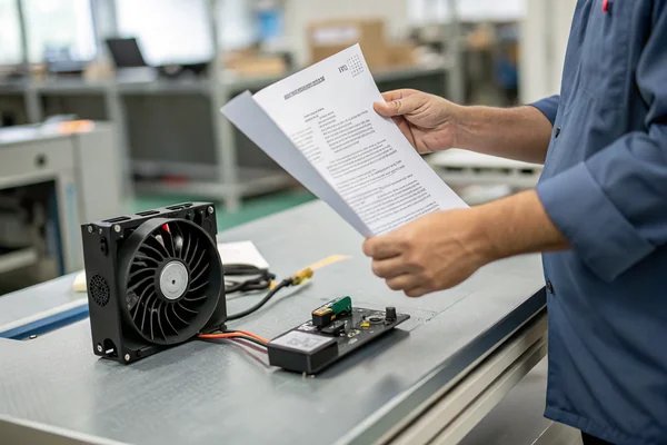
Cooling failures are usually silent failures -- the fan stops moving air and nothing tells you until the overheating damage is already done. The tach signal is the one thing that can catch it early.
- Tach signals give real-time RPM feedback, typically two pulses per revolution on a standard 4-wire fan.
- It's an open-collector output, so it needs a pull-up resistor before a microcontroller can read a usable voltage level from it.
- Timing the interval between pulses gives a more accurate instantaneous speed reading than just counting pulses over a fixed window.
- Failure detection depends on watching both signal presence and frequency -- no signal usually means an electrical failure, while a low frequency points to something mechanical.
- Getting this right in a real design means debouncing the tach input, setting sensible alarm thresholds, and accounting for the startup transient as the fan spins up from zero.
When cooling systems fail, they usually fail silently — until the overheating damage becomes obvious. After 30 years working with DC fans, I've found the most effective way to catch cooling problems early is monitoring fan speed through the tachometer signal. Yet I regularly see designs where this feedback sits unused, or worse, connected incorrectly so it provides false confidence instead of real monitoring.
The tach signal isn't just a "nice to have" feature for premium applications. In any system where fan failure could cause expensive downtime or component damage, speed monitoring becomes as critical as the cooling itself. If you're not yet familiar with the wiring conventions behind this signal, it helps to start with a DC axial fan wiring guide covering 2-pin, 3-pin, and 4-pin configurations before diving into the tach signal specifics below.
Table of Contents
What Is a Tachometer Output?
A tachometer output provides real-time speed feedback from a DC fan by generating electrical pulses proportional to shaft rotation. In standard 4-wire fans, this appears as the third wire (after +12V and ground), with PWM speed control as the fourth. The pin layout and signal behavior for this wire are formally defined by Intel's 4-Wire Pulse Width Modulation (PWM) Controlled Fans specification 1, which is the de facto industry reference most fan manufacturers, including Herays, design against.
The tach signal typically outputs 2 pulses per revolution for most axial fans, though some manufacturers use 1 or 4 pulses depending on the internal sensor design. This pulse train lets external circuits calculate RPM, detect fan failure, and verify that speed control commands are actually being followed. If you'd rather adjust speed directly through voltage instead of relying solely on PWM with tach feedback, it's worth comparing the two approaches in a PWM vs. voltage fan speed control guide to see which fits your system better.
What makes tach monitoring valuable isn't just knowing the current speed — it's detecting when that speed deviates from what it should be. A fan spinning at 1000 RPM when it should be at 3000 RPM indicates either a control problem or mechanical failure, both of which can be caught before thermal damage occurs.
How Does the Tach Signal Work?
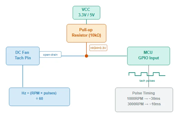
The tach signal is generated by a Hall effect sensor or optical interrupter inside the fan motor, triggered by magnets or slots on the rotating hub. Each time a trigger point passes the sensor, it pulls the tach output low briefly, then releases it to be pulled high by an external resistor.
This is an open-collector output, meaning the fan can only pull the signal to ground — it cannot drive it high. Without a pull-up resistor (typically 1kΩ to 10kΩ to the supply voltage), the tach line floats and produces no usable signal.
| Fan speed | Pulse frequency | Pulse period |
|---|---|---|
| 1000 RPM | ~33 Hz | ~30 ms |
| 2000 RPM | ~67 Hz | ~15 ms |
| 3000 RPM | ~100 Hz | ~10 ms |
| 4000 RPM | ~133 Hz | ~7.5 ms |
The relationship is straightforward: Frequency (Hz) = (RPM × pulses per revolution) ÷ 60. For a 2-pulse fan, every 1000 RPM increase adds roughly 33 Hz to the tach frequency.
How Do You Read Tach Signal with a Microcontroller?
Reading tach signals requires measuring either pulse frequency or pulse period. In my experience, period measurement (timing the interval between pulses) gives better real-time accuracy than frequency counting, especially when fan speed changes rapidly.
Here's the basic approach:
- Configure the microcontroller pin as a digital input with interrupt capability, typically triggered on falling edges
- Add a pull-up resistor (1kΩ - 10kΩ) from the tach line to the microcontroller's supply voltage
- Measure time intervals between consecutive pulses using a hardware timer
- Calculate RPM from the measured period: RPM = (60 × 1,000,000) ÷ (period_microseconds × pulses_per_revolution)
The advantage of period measurement is immediate response — you get an updated RPM reading with every pulse, rather than waiting for a counting window to complete. This matters during fan startup or when detecting rapid speed changes that indicate problems.
With more than 20 years of production and R&D experience, Herays manufactures DC axial fans as an OEM partner for several well-known brands, under a quality system certified to ISO 9001, ISO 14001, QC 080000, and IATF 16949. Our in-house magnetic field distribution tester helps ensure consistent tach signal timing across production batches — inconsistent magnetic positioning is one of the most common causes of erratic tach signals in field applications, which is why we validate the Hall sensor trigger points during final QC rather than relying on component specifications alone.
Signal conditioning considerations:
- Debounce the input to filter electrical noise, especially in high-EMI environments
- Set reasonable timeout limits — if no pulses arrive within 2-3 times the expected period, treat it as a stall or failure
- Account for startup transients — fans can take several hundred milliseconds to reach stable speed, during which tach readings will be erratic
How Do You Detect Fan Alarms and Locked Rotor Conditions?
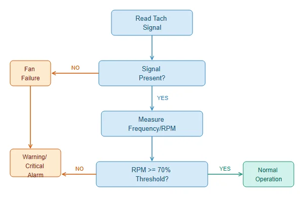
Fan failure detection requires monitoring both signal presence and signal frequency. The two main failure modes have different tach signatures:
Electrical failure (power loss, broken wire, failed motor driver): No tach signal at all. This is usually the easier case to detect — set a timeout period (e.g., 5 seconds) and trigger an alarm if no pulses arrive.
Mechanical failure (bearing seizure, blade obstruction, rotor imbalance): Tach signal present but frequency too low. This requires comparing measured RPM against expected RPM with appropriate tolerance bands. If you suspect a mechanical issue rather than a wiring fault, walking through a general DC axial fan testing and troubleshooting guide alongside the tach readings will usually isolate the cause faster than tach data alone.
| Failure type | Tach signal behavior | Detection method |
|---|---|---|
| Power loss | No pulses | Timeout-based (no pulses for >5 seconds) |
| Broken tach wire | No pulses | Timeout-based, but power consumption normal |
| Locked rotor | No pulses or very low frequency | Timeout + current monitoring |
| Bearing wear | Reduced speed, erratic timing | Speed below threshold, period variation |
| Blade obstruction | Intermittent low speed | Speed drops below minimum threshold |
Setting alarm thresholds: A common approach is to trigger warnings when measured RPM falls below 70-80% of the expected speed, and critical alarms below 50%. The exact thresholds depend on your application's thermal margins and how quickly overheating becomes dangerous.
How Do You Integrate Speed Monitoring in Your System?
Effective fan monitoring goes beyond just reading RPM — it needs to integrate with your system's overall health monitoring and respond appropriately to different failure scenarios.
System integration considerations:
- Centralized monitoring: If you have multiple fans, consider whether each needs individual monitoring or whether a few critical fans can represent overall cooling health
- Alarm escalation: Define what happens when a fan fails — immediate shutdown, switch to backup cooling, reduce system load, or just log the event
- Communication protocols: For networked systems, decide whether fan status needs to be reported via SNMP, Modbus, or other protocols
- User interface: Determine what fan information operators need to see — current RPM, failure alarms, historical trends, or maintenance schedules
Common implementation patterns:
- Simple threshold monitoring: Good RPM/Bad RPM, with basic alarm output
- Trend analysis: Log RPM over time to predict bearing wear before complete failure
- Load-adaptive monitoring: Adjust expected RPM based on current PWM duty cycle or system temperature
- Redundancy management: Automatically increase speed on remaining fans when one fails
For mission-critical applications, consider implementing both hardware and software monitoring paths — a dedicated fan controller IC as backup to microcontroller-based monitoring, so cooling oversight continues even if the main processor fails.
FAQ
What voltage levels should I expect on the tach signal? The tach output is open-collector, so it depends on your pull-up resistor and supply voltage. With a 5V supply and proper pull-up, expect 0V (low) to 5V (high) swings. With 3.3V systems, the high level will be 3.3V.
Why is my tach signal erratic or missing pulses? Common causes include missing or wrong-value pull-up resistor, electrical noise in high-EMI environments, loose connector, or inconsistent magnetic trigger positioning inside the fan. Try a different pull-up value (1kΩ-10kΩ range) and add signal filtering.
Can I use tach signals for precise speed control feedback? Yes, but the resolution is limited by the pulses per revolution (typically 2). For fine speed control, the tach signal provides feedback for closed-loop PWM adjustment, but don't expect precision better than ±50 RPM due to the discrete pulse nature.
How do I distinguish between a failed fan and a disconnected cable? Monitor both tach signal and power consumption if possible. A disconnected cable shows no tach signal and no current draw. A seized rotor shows no tach signal but higher than normal current as the motor stalls against the obstruction.
What's the typical response time for detecting fan failure? For electrical failures (no pulses), detection can be as fast as your timeout setting — typically 2-5 seconds. For mechanical failures (low speed), it depends on how far below threshold the fan needs to drop, usually 10-30 seconds for reliable detection without false alarms.
"4-Wire Pulse Width Modulation (PWM) Controlled Fans Specification" (Rev 1.3), https://www.konilabs.net/docs/standards/fan/intel_4wire_pwm_fans_specs_rev1_2.pdf. Intel's original public specification defining the 4-pin fan connector, including the open-collector tachometer output and PWM control signal used industry-wide. ↩

Liang
I've been working with DC fans for 30 years — long enough to have seen the industry evolve from basic sleeve bearing designs to today's high-efficiency, IP68-rated systems built for the harshest environments imaginable. I founded Herays because I believed manufacturers and engineers deserved a supplier who could talk technical from day one. Not just hand over a datasheet, but actually help you select the right fan for your thermal load, your enclosure, your certification requirements. Most of what I write here comes directly from problems I've solved on the factory floor or in customer applications — medical devices, laser equipment, industrial automation, you name it. If it involves moving air efficiently and reliably, I've probably spent time thinking about it. When I'm not obsessing over airflow curves, I'm usually helping a customer figure out why their cooling system isn't performing the way their simulation said it would.
View all posts by Liang