Picking the wrong blower size doesn't just leave performance on the table -- it can invalidate an entire thermal design before the first unit ships.
DC blower fan sizing follows different rules than axial fan sizing: the P-Q curve1 shifts dramatically with diameter and scroll geometry, meaning size selection must start with static pressure and duct constraints, not airflow volume alone.
- Blower fans are sized primarily against static pressure requirements and duct geometry, not against free-air CFM the way axial fans typically are.
- 50–60mm blowers suit compact, low-clearance enclosures where restricted airflow paths demand pressure over volume -- medical devices, handheld instruments, and dense PCB assemblies are common fits.
- 80–120mm blowers cover the higher-airflow tier: server rack cooling, industrial control panels, and larger enclosed equipment where both pressure and volume matter.
- Custom blower dimensions become justified when standard footprints conflict with enclosure geometry, mounting constraints, or specific pressure-curve requirements that off-the-shelf sizing can't match.
- Duct cross-section and housing inlet geometry interact with blower scroll design to set the effective operating point -- a correctly sized blower paired with a poorly matched duct loses a significant share of its rated performance.
Understanding where blower size actually enters the performance equation -- and where it doesn't -- is what separates a well-matched thermal design from one that gets reworked at the prototype stage.
Table of Contents
Why Does Blower Fan Sizing Work Differently Than Axial Fan Sizing?
Specifying a blower the same way you'd specify an axial fan is one of the most common thermal design mistakes made early in a project.
Axial fans are typically sized by free-air CFM at a relatively flat pressure curve, but blower fans move air perpendicular to their intake and develop steep pressure curves -- which means blower sizing must start with the system's static pressure requirement first, then match diameter and scroll geometry to that operating point.
The Geometry Is Fundamentally Different
An axial fan pulls air parallel to its rotational axis and exhausts it the same direction, making it most efficient in low-resistance, open-air paths. A blower fan, by contrast, draws air axially into a scroll housing and exhausts it perpendicular -- typically through a tangential outlet duct. This 90-degree redirection is why blowers develop substantially higher static pressure than an axial fan of similar diameter: the scroll housing converts rotational velocity into pressure rather than simply pushing a column of air forward.
This difference matters for sizing because the operating point on a blower's P-Q curve shifts much more aggressively with system resistance than on a comparable axial fan. A small increase in duct restriction can push an axial fan to the left on its curve while still delivering usable airflow; the same restriction on an underpowered blower can drop it nearly to stall. Choosing blower diameter and impeller width without first characterizing the system's resistance curve is designing blind.
| Parameter | Axial Fan Sizing Priority | Blower Fan Sizing Priority |
|---|---|---|
| Primary spec | Free-air CFM | Static pressure at operating point |
| Secondary spec | Noise at operating speed | Airflow volume through the duct |
| Geometry constraint | Mounting diameter | Scroll outlet dimensions + duct match |
| Failure mode | Airflow starvation in open paths | Pressure stall in restricted ducts |
Why This Changes the Selection Workflow
In practice, sizing a blower starts by calculating the system's expected pressure drop across the full airflow path -- filters, duct bends, heat exchanger resistance, and any louver or grille restrictions. That calculated pressure requirement sets the minimum P-Q curve intersection the blower must deliver. Only once that pressure floor is established does diameter selection enter the picture, as a larger diameter primarily adds airflow volume at the required pressure point rather than changing the shape of the curve fundamentally.
What Are 50–60mm Blowers Actually Best At?
Compact blowers in the 50–60mm range get specified into tight enclosures where the available footprint rules out larger alternatives, but the airflow path is too restricted for any axial fan to work effectively.
50–60mm DC blowers are optimized for confined, high-resistance airflow paths in compact equipment: medical diagnostics, handheld instruments, and dense PCB enclosures where the combination of limited physical space and high static pressure demand makes a small-diameter blower the only practical option.
Where Compact Blowers Fit and Where They Don't
The 50mm class typically delivers static pressure in a range that handles moderate-restriction paths -- internal ducting with one or two bends, a thin HEPA or ULPA filter, or a closely spaced fin stack on a heat sink. The 60mm class extends that range incrementally, with the added scroll width allowing slightly higher impeller tip speed for the same noise budget. Both sizes are commonly found in continuous-duty medical equipment (CPAP and BiPAP devices are a classic example), point-of-care diagnostic instruments, and industrial handheld scanners where the enclosure geometry physically can't accommodate an 80mm unit.
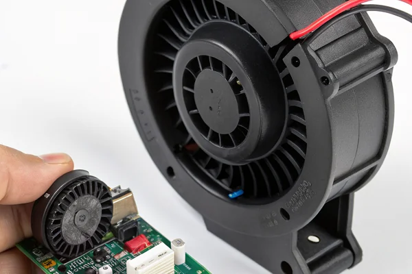
What compact blowers cannot do well is substitute for larger blowers in high-airflow applications by simply running faster. Spinning a 50mm impeller faster does increase pressure, but also increases noise disproportionately because tip speed noise scales with roughly the fifth power of velocity -- a design truth that makes "just speed it up" an expensive acoustic mistake at this size class. Specifying a 50–60mm blower correctly means accepting its airflow ceiling as a real constraint and designing the thermal path around it, rather than treating speed as a free performance lever.
What Do 80–120mm Blowers Enable That Smaller Sizes Can't?
Moving up to the 80–120mm range isn't just about more airflow -- it changes what categories of equipment can be cooled with a blower topology at all.
80–120mm DC blowers serve higher-airflow applications where both meaningful static pressure and substantial volume are required simultaneously: server infrastructure, industrial control cabinets, medical imaging equipment, and rack-mounted instrumentation where the thermal load and duct geometry demand more than any compact blower can supply.
How the Larger Scroll Changes the Performance Character
At 80mm and above, the impeller can develop significantly more airflow volume while maintaining pressure levels that handle the moderately restrictive paths common in rack-mounted or cabinet equipment. The wider scroll housing also allows a more gradual velocity-to-pressure conversion, which in well-designed units translates into a flatter P-Q curve through the mid-range operating zone -- a practical benefit for systems where the actual operating point isn't precisely predictable at design time.
The 120mm class represents roughly the upper practical limit for standard DC blower sizing in most industrial applications. Above this size, thermal designers typically transition to centrifugal blower assemblies or multi-fan arrays rather than a single blower unit, partly because motor torque requirements at large impeller diameters make single-unit 24V DC supply management more difficult and partly because mounting a single large-scroll blower introduces mechanical resonance risks in equipment with vibration-sensitive components.
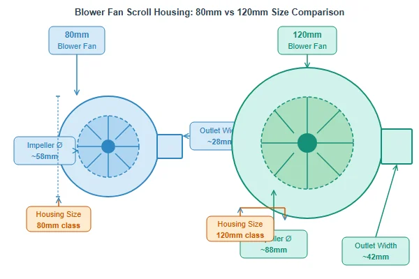
| Size Class | Typical Static Pressure Range | Typical CFM Range | Common Applications |
|---|---|---|---|
| 50–60mm | Moderate | Lower | Medical devices, handheld instruments |
| 80mm | Moderate-high | Medium | Small server units, rack instruments |
| 120mm | High | Higher | Industrial cabinets, imaging equipment |
When Does a Custom Blower Dimension Actually Justify the Added Cost?
Custom tooling for a non-standard blower size is a real cost, and it's frequently requested for the wrong reasons.
Custom blower dimensions are justified when a standard footprint creates a genuine mechanical conflict -- mounting geometry, outlet duct alignment, or a pressure-curve requirement that no off-the-shelf size can match -- but they're rarely justified by airflow or noise targets alone, which standard sizes can usually meet through impeller and speed optimization.
The Honest Cost-Benefit Threshold
The primary cost driver in a custom blower is the scroll housing tooling, since the housing is typically injection-molded and a custom geometry requires a new mold. For volume programs above a meaningful threshold, that tooling cost amortizes across units quickly enough to be commercially viable. Below that threshold, the tooling cost per unit can exceed any BOM savings the custom dimension provides, which is why standard sizes are almost always the right starting point and custom dimensions are a last resort after exhausting standard options.
Where custom dimensions genuinely pay off is in applications with unusual form factors: a slot-mounted instrument with a fixed 67mm horizontal clearance, an enclosure where the outlet duct must exit at a non-standard angle, or medical equipment where the blower must integrate with a custom filter housing of specified dimensions. In these cases, the alternative to custom tooling is usually a worse mechanical compromise -- shimming, bracket adapters, or airflow path modifications that hurt performance more than custom tooling costs.
How Do Duct and Enclosure Constraints Actually Set the Effective Operating Point?
A blower sized correctly on paper can still underperform significantly if the duct geometry feeding and exhausting it isn't accounted for.
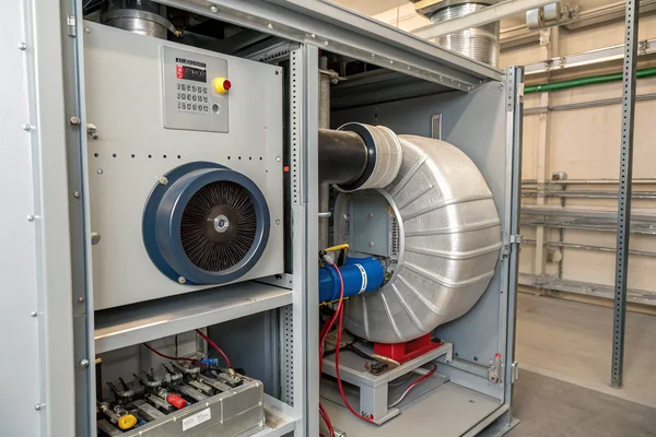
Duct cross-section, inlet clearance, and outlet transition geometry all shift a blower's effective operating point away from its rated P-Q curve -- which means enclosure design and blower selection must be developed together, not sequentially, to avoid discovering a performance gap at the integration stage.
The Inlet Side Matters as Much as the Outlet
Most engineers focus on outlet duct resistance when calculating system pressure drop, but inlet conditions contribute meaningfully to a blower's real-world performance. A blower drawing air through an undersized inlet opening, a sharp-edged aperture, or a plenum with too little depth before the impeller develops inlet turbulence that reduces effective pressure development even before the air enters the scroll. The general design rule -- providing an inlet clearance of at least the impeller diameter where possible -- exists because violating it imposes a performance penalty that can be difficult to recover through speed adjustments alone.
On the outlet side, transitions from the blower's tangential duct outlet to the system's airflow path introduce pressure losses whenever the cross-section changes abruptly, a bend occurs within a short duct length, or the outlet velocity is significantly higher than the downstream duct velocity. These losses accumulate into a system resistance curve that, when plotted against the blower's rated P-Q curve, defines the actual operating point -- which is almost always at a lower airflow than the blower's free-air CFM rating suggests.
What Should the Procurement Conversation Actually Cover When Sourcing a Blower?
Sourcing a blower from a supplier using only a datasheet comparison misses the specs that most often determine whether the fan fits the application.
When sourcing DC blowers, the procurement conversation needs to cover the system's actual static pressure operating point, inlet and outlet duct geometry, voltage tolerance range, and duty cycle -- not just nominal CFM and size class -- because these are the parameters that determine whether a supplier's standard offering can be directly applied or needs modification.
Beyond the Datasheet: What to Ask and Why
Standard blower datasheets typically publish free-air CFM, maximum static pressure, rated voltage, current draw, and noise level at a single operating point. None of those numbers directly tells you where on the P-Q curve the blower will actually run in a specific enclosure, or whether the scroll outlet dimensions match the duct you've designed. Asking a supplier for the full P-Q curve across the voltage range -- not just at nominal voltage -- reveals how sensitive the operating point is to supply variation, which matters for battery-powered or wide-input equipment.
Duty cycle and operating temperature range are equally important procurement conversations that often happen too late. A blower rated for a given noise level at 25°C ambient running continuous duty is a different product from one intended for intermittent operation in a 55°C environment -- not always labeled differently on a shelf, but genuinely different in terms of bearing specification, motor winding, and expected service life. Asking these questions at the RFQ stage, rather than after first-article testing, is what separates a smooth production ramp from a re-qualification cycle.
Our DC High-Speed Vortex Blower Fan line spans compact to larger-format sizes, and every unit is validated against its rated P-Q curve on our in-house CFM airflow test system as part of our ISO 9001 and IATF 16949 quality process. When the standard size range doesn't match your enclosure geometry or pressure requirements, our Dongguan engineering team can discuss custom scroll geometry and impeller options backed by 20+ years of blower R&D -- we'd rather have that conversation at your RFQ stage than after a prototype integration issue.
FAQ
Does blower fan diameter alone determine its static pressure capability?
No -- scroll housing depth, impeller blade geometry, and rotational speed all contribute to static pressure capability alongside diameter. Two blowers of the same diameter with different scroll designs can have substantially different P-Q curves.
Can a DC blower fan replace an axial fan in the same mounting hole?
Generally not without modification. Blowers exhaust perpendicular to their intake, so they require duct outlets that axial fan cutouts don't provide. The mounting footprints are also rarely interchangeable.
How is blower noise different from axial fan noise at the same size?
Blower noise is typically dominated by scroll outlet tones and turbulence at the duct transition rather than blade-tip noise, which gives it a different acoustic character -- often a higher-frequency tonal component that can be more noticeable in quiet environments even at similar dB(A) ratings.
What voltage options are typical for DC blowers in industrial applications?
5V, 12V, and 24V are the most common DC blower voltages. 24V units are preferred in industrial control cabinet applications for compatibility with standard DIN rail power supplies and reduced current draw at a given power level.
Is bearing type more important for blowers than for axial fans?
Bearing specification matters comparably, but blowers often see higher operating temperatures due to their enclosed scroll housing and are more frequently specified for continuous duty -- both factors that favor ball bearing or fluid dynamic bearing specifications over sleeve bearings for longer service life.
How much does custom tooling typically add to the per-unit cost at production volumes?
Tooling cost structure varies by geometry and material, but as a general rule, custom scroll housing tooling amortizes to a small per-unit addition at volumes in the thousands and above. At low volumes, it can dominate the unit cost. This is why the standard-size-first evaluation is always worth completing before requesting custom tooling.
Should blower fans be tested to ANSI/AMCA Standard 2102 for P-Q curve validation?
AMCA 210 defines the laboratory method for fan P-Q curve testing and is the recognized reference for aerodynamic performance validation. For critical applications, specifying that supplier P-Q data is generated to AMCA 210 methodology gives you a consistent basis for comparing curves across sources.
Blower fan size sets the boundaries of what a thermal design can achieve, but only if the selection starts with the right inputs -- static pressure first, duct geometry second, diameter third. At Herays, our Dongguan facility has engineered DC blower fans for 20+ years under ISO 9001, ISO 14001, and IATF 16949 certification. If your application has a specific pressure requirement or a tight enclosure constraint, we're glad to work through the sizing with you before a prototype proves the mismatch.
P-Q curve is the graphical relationship between static pressure and airflow volume for a fan at a given speed, showing how delivered airflow decreases as system resistance (back-pressure) increases. For blower fans, this curve is steeper than for comparable axial fans and is the primary tool for predicting real operating performance in a specific system. ↩
ANSI/AMCA Standard 210 establishes the laboratory test methods for measuring fan aerodynamic performance including airflow and static pressure, providing a standardized basis for comparing P-Q data across different manufacturers and fan types. ↩

Liang
I've been working with DC fans for 30 years — long enough to have seen the industry evolve from basic sleeve bearing designs to today's high-efficiency, IP68-rated systems built for the harshest environments imaginable. I founded Herays because I believed manufacturers and engineers deserved a supplier who could talk technical from day one. Not just hand over a datasheet, but actually help you select the right fan for your thermal load, your enclosure, your certification requirements. Most of what I write here comes directly from problems I've solved on the factory floor or in customer applications — medical devices, laser equipment, industrial automation, you name it. If it involves moving air efficiently and reliably, I've probably spent time thinking about it. When I'm not obsessing over airflow curves, I'm usually helping a customer figure out why their cooling system isn't performing the way their simulation said it would.
View all posts by Liang